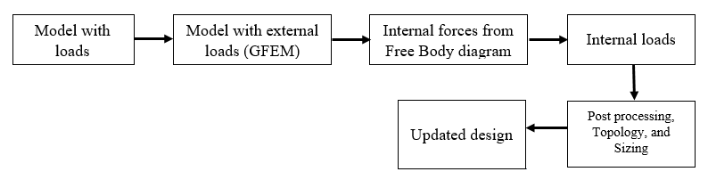
The accuracy of the Finite Element Model required for structural analysis changes
throughout the design process. The flow chart below explains the process of
structural analysis of an aircraft briefly.Figure 1. Overview of the Design and Analysis of Aircrafts
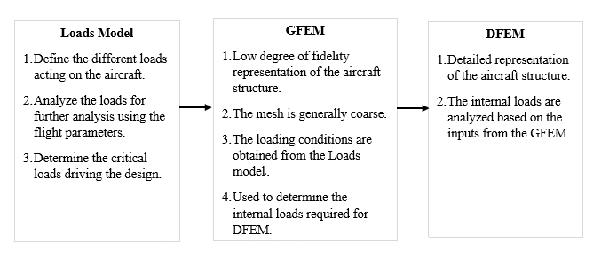
In general determination of design, loads are the first step in the design and
analysis of an aircraft. Initially, a structural design criterion is developed which
accounts for the loads coming from the different operating conditions of the
aircraft, flight parameters and any additional loads specified by the customer.
Based on these inputs and considering the aerodynamics and flight masses, an overall
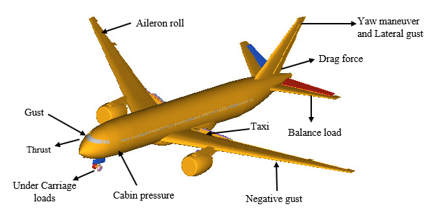
load case data is generated. Figure 1 shows some of the different aircraft loads
that an aircraft is subjected during its flight, apart from these some of the other
load cases that are to be considered include vibrations, acoustic noise, system
pressures, different maneuvers and loads during ground handling. Not all of these
load cases contribute to the design process and; therefore, it is important to
determine the load cases that are critical to the design. These loads are analyzed
multiple times for each time step to determine the critical loads accounting for the
design changes. This process helps the load engineers in determining the detailed
critical loads of specific loads.Figure 2. Different Loads Acting on an Aircraft Figure 3. Modeling Process
Global Finite Element Model (GFEM)
The next step of the design process, a Global Finite Element Model (GFEM) or an
External Loads model is developed, which is further used to analyze the external
loads obtained previously. The GFEM model is a simplistic representation of the
aircraft structure mostly made up of idealized frames, panels, and stringers that
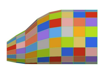
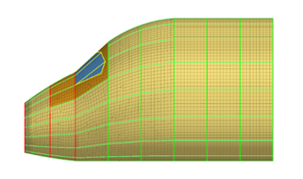
are represented by a coarse mesh with the use of shell and bar elements. Figure 4 shows a GFEM model of a fuselage nose
section, in which the panels are represented as one single element with stringers
and a frame being modeled using 1D elements. In most cases, each component of an
aircraft is analyzed separately with loads applied at the reference stations. These
reference stations have Multi-Point Constraints (MPCs) defined that link the grid
points of the reference station to the frames. Generally, after all the external
load cases are analyzed, the internal loads corresponding to these analyses can be
requested and used for a detailed analysis.Figure 4. GFEM Representation of a Fuselage Nose Section
Detailed Finite Element Model (DFEM)
In this stage of the analysis, a more detailed model of the aircraft is developed,
and the internal loads obtained from the GFEM are applied to the components to
analyze the response. Mostly, at this stage, the 1D models are replaced with more
precise 2D and 3D representation. For example, the flanges which were initially
represented as a 1D element in GFEM would be updated with a 2D model in a DFEM
process to obtain a 3D representation of the flange. In the subsequent sections,
some of the tools and processes that can be used for DFEM simulation are
discussed.Figure 5. DFEM Representation of a Fuselage Nose Section
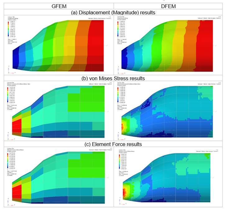
The results from GFEM and DFEM have been compared as:Figure 6. Comparison of Results from GFEM and DFEM