
Separated Laminar Flow Over a Blunt Plate
In this application, AcuSolve is used to simulate the separation of laminar flow over a blunt plate. AcuSolve results are compared with experimental results as described in J.C. Lane and R.I. Loehrke (1980). The close agreement of AcuSolve results with the experimental results validates the ability of AcuSolve to model cases with external laminar flow including separation.
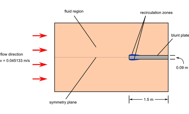
Problem Description
AcuSolve Results
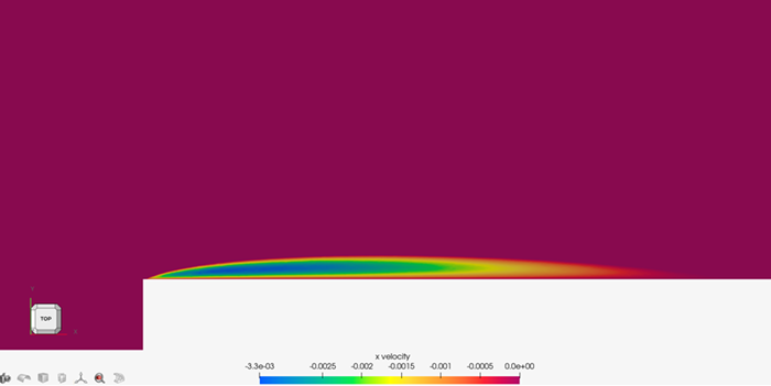
Downstream of the leading edge, the flow eventually reattaches to the plate at the point where the shear stress parallel to the wall passes from negative through zero to positive. The reattachment point is 0.37 m from the leading edge of the plate and corresponds to the trailing edge of the contours.
| AcuSolve xreattach | AcuSolve xreattach/T | Experimental xreattach/T | Percent error (%) |
|---|---|---|---|
| 0.37 | 4.11 | 4.0 | 2.8 |
Summary
In this application, a constant flow inlet velocity and symmetric boundary conditions were used to model 2D flow over a blunt plate. The AcuSolve solution compares well with experimental results for the separation of laminar flow over a blunt plate. The non-dimensional reattachment length obtained from the AcuSolve steady state solution compares well with the experimental solution, with an error of less than 3.0 percent. The results of this simulation validate the ability of AcuSolve to accurately predict the reattachment point in cases with external, laminar flow with separation.
Simulation Settings for Separated Laminar Flow over a Blunt Plate
HyperMesh CFD database file: <your working directory>\blunt_plate_laminar\blunt_plate_laminar.hm
Global
- Problem Description
- Analysis type - Steady State
- Turbulence equation - Laminar
- Auto Solution Strategy
- Relaxation Factor - 0.2
- Material Model
- Fluid
- Density - 1.0 kg/m3
- Viscosity - 1.7894e-005 kg/m-sec
Model
- Fluid
- Volumes
- Fluid
- Element Set
- Material model - Fluid
- Element Set
- Fluid
- Surfaces
- Back
- Simple Boundary Condition
- Type - Symmetry
- Simple Boundary Condition
- Freestream
- Simple Boundary Condition
- Type - Slip
- Simple Boundary Condition
- Front
- Simple Boundary Condition
- Type - Symmetry
- Simple Boundary Condition
- Inlet
- Simple Boundary Condition
- Type - Inflow
- Inflow type - Velocity
- Inflow velocity type - Cartesian
- X Velocity - 0.045133 m/s
- Simple Boundary Condition
- Outflow
- Simple Boundary Condition
- Type - Outflow
- Simple Boundary Condition
- Plate
- Simple Boundary Condition
- Type - Wall
- Simple Boundary Condition
- Symmetry
- Simple Boundary Condition
- Type - Symmetry
- Simple Boundary Condition
- Back
References
J.C. Lane and R.I. Loehrke. "Leading Edge Separation from a Blunt Plate at Low Reynolds Number". Journal of Fluids Engineering. 102(4):494-496. 1980.