Flow Inside a Rotating Cavity
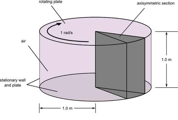
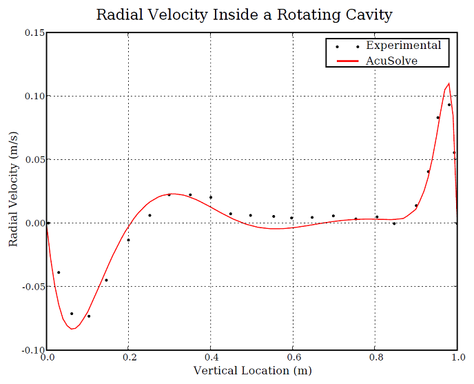
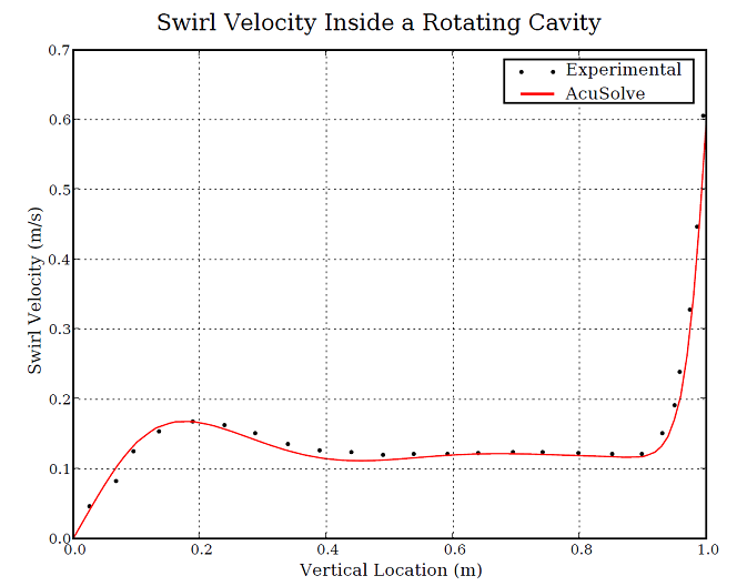
In this application, AcuSolve is used to simulate the flow of air in an enclosed cylindrical cavity with a rotating top and a fixed bottom. AcuSolve results are compared with experimental data adapted from Michelsen (1986). The close agreement of AcuSolve results with experimental data validates the ability of AcuSolve to model cases containing enclosed cavities with flow induced by rotating walls.
Problem Description
AcuSolve Results

Summary
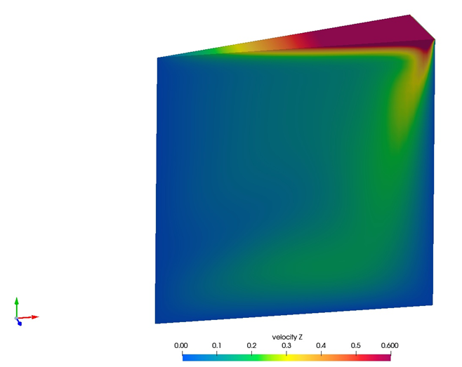
The AcuSolve solution compares well with the experimental data for flow induced by a rotating top of an enclosed cylinder. In this application, the flow in the fluid region is driven by the viscous stresses near the rotating top. Viscous stresses drag the fluid in a circular direction near the spinning wall. The angular velocity of the fluid decreases as distance from the top wall increases. Radial velocity develops as a result of the migration of the fluid toward the outer wall in regions of high angular velocity. The AcuSolve radial and swirl velocities compare very closely with the experimental data.
Simulation Settings for Flow Inside a Rotating Cavity
SimLab database file: <your working directory>\cavity_rotating\cavity_rotating.slb
Global
- Problem Description
- Solution type - Steady State
- Flow - Laminar
- Auto Solution Strategy
- Relaxation Factor - 0.4
- Material Model
- Air
- Density - 1.0 kg/m3
- Viscosity - 0.000556 kg/m-sec
- Air
- Reference Frame
- Cavity Rotation
- Rotation center
- X-coordinate - 0.0
- Y-coordinate - 0.0
- Z-coordinate - 0.0
- Angular velocity
- X-component - 0.0
- Y-component - -1.0 rad/sec
- Z-component - 0.0
- Rotation center
Model
- Cavity Rotation
- Volumes
- Fluid
- Element Set
- Material model - Air
- Element Set
- Fluid
- Surfaces
- Bottom
- Simple Boundary Condition
- Type - Wall
- Simple Boundary Condition
- Max_X
- Simple Boundary Condition
- Type - Wall
- Simple Boundary Condition
- Max_Z
- Simple Boundary Condition - (disabled to allow for periodic conditions to be set)
- Min_Z
- Simple Boundary Condition - (disabled to allow for periodic conditions to be set)
- Top
- Simple Boundary Condition
- Type - Wall
- Reference frame - Cavity Rotation
- Simple Boundary Condition
- Bottom
- Periodics
- Periodic 1
- Periodic Boundary Condition
- Type - Axisymmetric
- Rotation axis
- point 1
- X-coordinate - 0.0 m
- Y-coordinate - 0.0 m
- Z-coordinate - 0.0 m
- point 2
- X-coordinate - 0.0 m
- Y-coordinate - 1.0 m
- Z-coordinate - 0.0 m
- point 1
- Periodic Boundary Condition
- Periodic 1
References
J. A. Michelsen. "Modeling of Laminar Incompressible Rotating Fluid Flow". AFM 86-05. Ph.D. thesis, Department of Fluid Mechanics, Technical University of Denmark. 1986.