Since version 2026, Flux 3D and Flux PEEC are no longer available.
Please use SimLab to create a new 3D project or to import an existing Flux 3D project.
Please use SimLab to create a new PEEC project (not possible to import an existing Flux PEEC project).
/!\ Documentation updates are in progress – some mentions of 3D may still appear.
Orientation of components
Introduction
The orientation of the components in the electrical circuit is carried out by observing the sign conventions expressed hereafter.
Orientation reference: sign convention
To orient the components, we will note the presence of a mark-square symbol, on one of the points of the components (excepting the macro-component, squirrel cage, that has a single point).

By convention:
-
the voltage U at the terminals of a component is given in function of the two potentials by the relationship:
U = Vhot point – Vcold point
- the current flowing through a component is positive when it enters via the hot point

Orientation of sources
The orientation of sources defines the direction of the current through the electrical circuit.
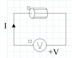
- Voltage source (with U > 0): the current exits via the hot point
With the convention:
- generator: U > 0 and I > 0
- receptor: U > 0 and I < 0 (Flux 2D)
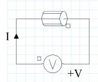
- Current source (with I > 0): the current enters via the hot point

With the convention:
- generator: I > 0 and U > 0
- receptor: I > 0 and U < 0 (Flux 2D)
- In Flux 2D the convention receptor is used for the components assembly (generator and receptor).
- In Flux 3D, the convention receptor is used for the assembly of the receptor components. Concerning the generator components: the current through the voltage source, as well as the voltage in a current source, is not computed.
Example
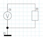
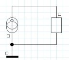
Two circuit examples, with voltage source and with current source, are shown in the figure below.
-
Circuit with voltage source V1 > 0:
-
Circuit with current source I1 > 0:
Orientation of the sources and supplied power
In Flux 2D, the receptor convention is used for the sources (current source and voltage source). Hence, the power computed in the source components is negative.
In an electrical circuit, the sum of the electrical powers is always null (observing the principle: “nothing is lost, nothing is created”). The sum of the powers (negative) supplied by the sources is equal to the sum of power (positive) lost in different components.
Orientation of the conductors (2D)
The orientation of the conductor components in the electrical circuit defines the direction of the current in the related regions of the finite element domain.
In the conducting regions of the finite element domain the current is normal to the plane of the figure.
| Conductor positively oriented | Conductor negatively oriented |
|---|---|
|
|

|
 |
|
I positive: the current flows from the back to the front of the figure |
I negative: the current flows from the front to the back of the figure |
Orientation of the conductors (3D)
The orientation of the conductor components in the electrical circuit defines the direction of the current in the related regions of the finite element domain.
The direction of the current in the coils is defined by:
- the arrow direction on the non-meshed coils
- the definition of the entering and of the exiting faces or of the orientation line for the non-meshed coils (region of stranded conductor type)
| Conductor positively oriented | Conductor negatively oriented |
|---|---|

|

|
 |
 |
|
I positive: the current flows from the entering terminal towards the exiting terminal |
I negative: the current flows from the exiting terminal towards the entering terminal |