Flux 2022.3: New and Updated Macros
Here the list of new and updated macros implemented in the Flux 2022.3 release.
DisplayEntitiesofVolumeRegions.PFM (New)
This macro allows to set visible entities of one or several volume regions. The user will have the choice to display for the volume regions, the points, the line, the face, the volumes, an option is added to hide or not already displayed entities.

Input:
- Volume regions
- Entities to display for the selected volume regions
- Points
- Lines
- Faces
- Volumes
Output:
- Displayed the selected entities
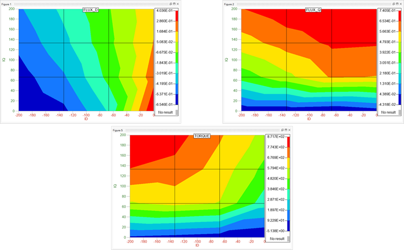
LUT_3D_4SystemAnalysis.PFM and LUT_Skew_4SystemAnalysis (New)
Adaptation of the LUT_2D_4SystemAnalysis macro for 3D and Skew projects. These macros can be found in the Macros_4SystemAnalysis directory. The macro for 2D has been created in Flux 2022.2, and the macro for 3D and the macro for Skew have been created in this Flux 2022.3 release (see Flux coupling with System Analysis software).
It works the same way as CreateLookUpTableFromTMProjectDQLight with additional export options: Look up table can be either written in a .mat format that can be read by Activate or PSIM. This macro has been created to make system analysis of your e-motors easier.
Those macros create look up table of φDQ, LD, LQ and torque versus ID, IQ and rotor position. It will create a new Magneto-Static project from the magnetic transient one. In the Magneto-Static project the current is driven with ID and IQ allowing to extract easily all the needed tables. At the end of the oml file in comment there is the possibility to display LD, LQ and torque versus ID and IQ with Altair Compose.
The outputs written in a .mat file that can be read for Flux-Activate/PSIM coupling. This macro has been created to make system analysis of your e-motors easier.
Input:
- Current in 3 supplies
- Select mobile mechanical set
- Select fixed mechanical set
- Max value for Id
- Number of values for Id (odd)
- Number of poles
- Number of pole pairs represented in geometry (0.5 for one pole)
- Number of stator periodicities
- Depending on rotor position
- Fast computation or not
- Number of steps in the electric period
- Period for rotation (in degrees)
- Motor viscuous friction coefficient (Nms/degrees)
- Motor inertia (in kg/m²)
Output:
- Create a result OML file with name created from the initial file (*_res.oml)
- It will also include more data such as phase resistance, end winding inductance, electric period and initial rotor position plus possibility to display values in Compose
ExportForcePerTooth3DToCSV.PFM and ExportForcePerTooth3DToCSVSingleFile.PFM (New)
Adaptation of the ExportForcePerTooth2DToCSV and ExportForcePerTooth2DToCSVSingleFile macro for 3D projects. These macros can be found in the Macros_Flux3D_Postproc directory.
This macro exports force by tooth in a general-purpose CSV format. It is useful for 3D transient applications representing rotating machines. Theses macros work with multispeed projects:
- ExportForcePerTooth3DToCSVSingleFile exports each speed in a different file
- ExportForcePerTooth3DToCSV exports all speeds in a unique file

Forces are computed, using the Flux data import/export context dedicated to mechanical coupling, on a support that is defined by the user
Macro for exporting force by tooth in general-purpose CSV format. Useful for 3D models of rotating machines.Output files contains the following data: Speed (rpm), Torque (Nm), Tooth_number, tooth coordinates (x, y, z), Time(s), Normal force(N), Tangential force(N) and Axial force(N).
Previous steps to call the macro:
1. Run the full transient analysis (at least one complete electric period)
2. Open I/O context (mechanical) and create or import support to calculate forces
3. Create data collection: forces for rotating machines using the previous I/O context.
4. Evaluate the data collection
5. Run the macro
Input:- Solved scenario
- A force data collection associated with previous scenario
- The pilot parameter (if any)
- The rotor position variable
- Rotor position min and max limits to identify the time instant that will be exported
- The root of the file name for the CSV files
- The selection of the type of analysis desired, frequential or temporal.
- One CSV file for each value of pilot param, each of them will contain a table with six columns: number of the tooth, tooth coordinates (x, y ,z), frequency/time, normal force and tangential force