Feed-forward and Mission Controller
Create a Controller Subtype in the Graphical User Interface
Controllers work like components in Flow Simulator; a controller doesn’t have a chamber association. You can drag-and-drop a controller from the Element Library.
- From the list, select the type Relation 1.Each relation type, described below, manipulates variables differently
- Constant
- Define a constant value for the Manipulated Variables.
- Linear Equation
- Manipulate a parameter as a function of a linear relation (slope and intercept) with gauge variables.
- Polynomial
- Define a polynomial relation between manipulation and gauge variables.
- Table1D
- Manipulate a parameter with a 1D table definition (for example, Time versus Static Pressure).
- Table2D
- Manipulate a variable as a function of a 2D table as input (for example, pump volumetric efficiency using delta pressure and pump RPM).
- ETA
- Manipulate a parameter with ETA functions.
-
Figure 3. 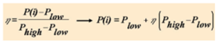
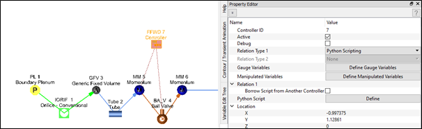
- Python Scripting
- In Flow Simulator, use Python scripting to define relations related to gauge and manipulated variables.
- Mission Transfer
- Transfer a value from a mission parameter to a manipulated variable.
-
Figure 4. 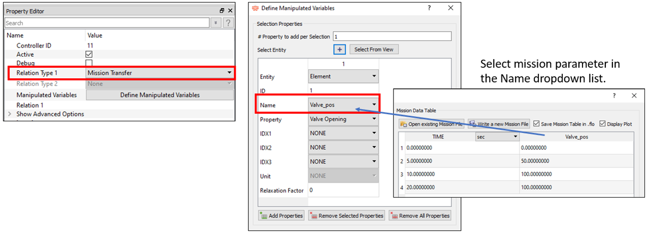
Add Gauge and Manipulated Variables
Defining gauge and manipulated variables using the Define Gauge Variables and Define Manipulated Variables options are similar. Both options are explained in this section.
- Use the Select Entity or Add
Properties menu to add entities.
- Define the number of properties to add per selection option if you
are adding more than one property for each selection. For example,
in the figure below, three GAUGE values are added for the selected
chamber, number 6.
Figure 5. 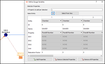
- If you select Select Entity, then the
Object Selection window is displayed. From
here, enter the object ID in the Selection
Range section.
- You can select more than one object. Use “,” to select the item ID or use “-“ to define a range.
- Objects are selected based on the selected Object
Type.
Figure 6. 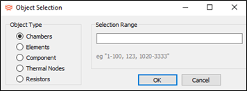
- Click Select from View to select objects from the Flow Simulator model window. Select objects until the Select from View icon is clicked again or the Define Gauge Variables window is closed.
- If you select Add Properties, empty
Gauge or Manipulated
columns are created. Define each item. In the example below, two
properties were created and assigned to the General Data and Mission variables.
Figure 7. 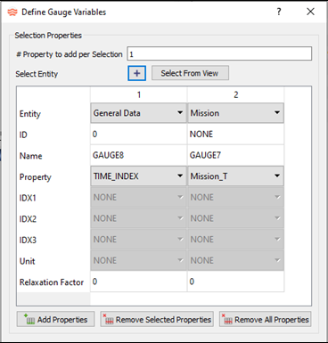
- Define the number of properties to add per selection option if you
are adding more than one property for each selection. For example,
in the figure below, three GAUGE values are added for the selected
chamber, number 6.
- Gauge and Manipulated variables contain the following fields:
- Entity: Chamber, Element, Component, Thermal Component, General
Data, Mission, Stored, and Controller.Note: Use the Mission parameter for the Gauge variable, but only for Transient and Quasi-steady Analysis. Quasi-steady means a steady-state analysis is performed, but the "run" time is used in controllers.
- ID: The ID of the object for flow objects, or thermal network ID for thermal components.
- Name: The Gauge/Manipulation Variable name. Customize the variable name for better use in tables and Python scripting.
- Property: Gauge or Manipulated property of the object.
- IDX1: Specific property types. For example, the station number for some Tube element properties, or Combination Flow Element flow fraction table row numbers, or the Thermal Component type: Tnode, Conductor, Convector, Radiator, or Heat Flow.
- IDX2: Specific property types. For example, circumferential wall side ID for some Incompressible Tube properties, or Thermal Component ID.
- IDX3: Specific property types. For example, left or right emissivity value of a two surface radiator.
- Unit: Selectable unit of each property, used to define inputs in the selected unit. The property values are converted to this unit before sending it to a Python script. If it’s a manipulated variable, Flow Simulator expects the variable to have this unit when returned from the Python script.
- Relaxation Factor: Relaxation factors for Gauge or Manipulated
variables.
- Controller relaxation may help the convergence of models with controllers.
- Apply relaxation to Gauge and/or Manipulated variables.
- Relaxation Factor range (.01 to 1.0)
- .01 – Low relaxation (only 1% of new value is used)
- 1.0 – No relaxation (all of new value used)
- Default is No Relaxation (0 in the Relaxation Factor field)
- Entity: Chamber, Element, Component, Thermal Component, General
Data, Mission, Stored, and Controller.
- Additional options include Remove Selected Properties and Remove All Properties.
- The gauge and manipulated variable tables allow multi-editing of the
property or unit inputs.
Figure 8. 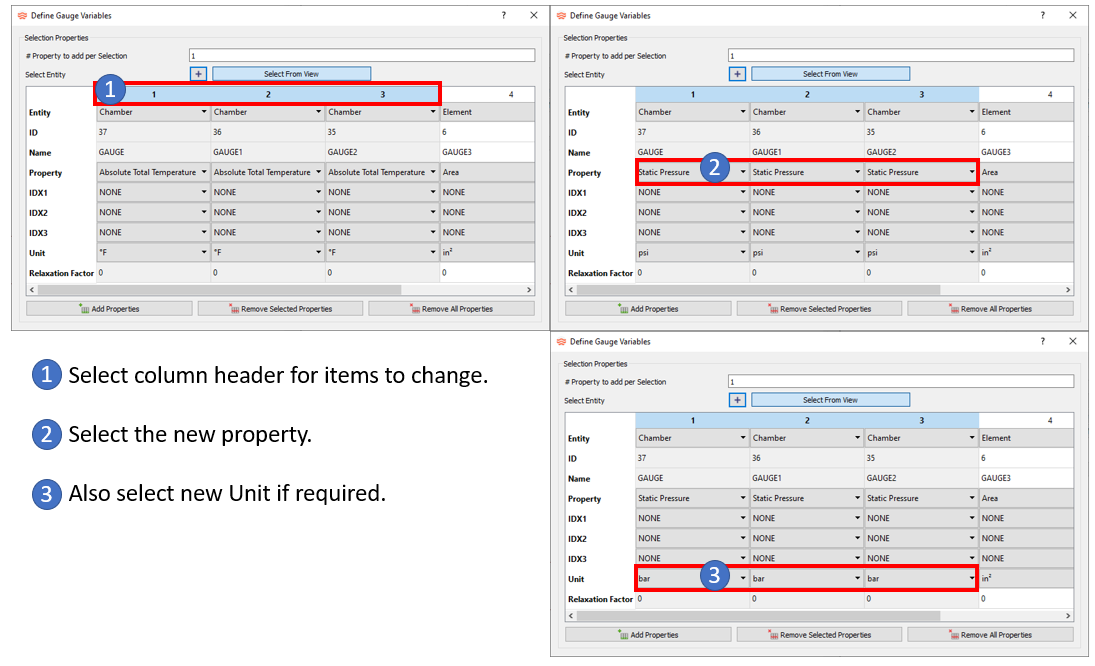
| Relation-1 | Number of Gauge | Number of Manipulated |
|---|---|---|
| Constant | 0 | 1 |
| Liner Equation | Multiple | 1 |
| Polynomial | 1 | 1 |
| TABLE1D | 1 | Multiple |
| TABLE2D | 2 | 1 |
| ETA | 3 | 1 |
| Python Scripting | Multiple | Multiple |
| Mission Transfer | None | Multiple |
Processing Control
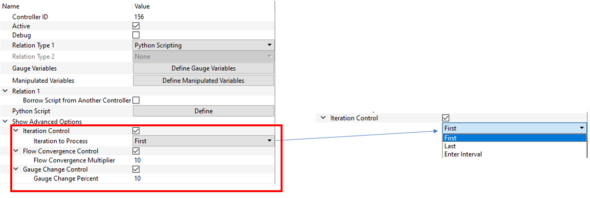
- Iteration Control: Run the controller at specified iterations. Use this instead of adding iteration checks to Python.
- Flow Convergence Control: Run the controller when flow convergence has reached a multiple of the convergence target. Ten times is default.
- Gauge Change Control: Run the controller when gauge variables have changed
more than a given percentage since the last controller run. If multiple
controls are active, the controller is processed if any of the controls are
“true”.
If the controller is not run, then manipulated variables remain at the same value as the previous controller run.
Controller Input
| Index | UI Name (. flo label) | Description |
|---|---|---|
| 1 | Type (CPTYPE) | Component Type. 5=Controller |
| 2 | (SUBTYPE) | The type of controller: “FEEDFWD”, “PID” |
| 3 | Active (ACTIVE) | Active or Inactive option for the controller |
| 4 | Debug (DEBUG) | ON: Display detailed controller calculation results in the
*.res file. OFF: Only the output of the controller properties are displayed. |
| 5 | Relation Type 1 (RELATION1) | “TABLE1D”, “TABLE2D”, “CONSTANT”, “LINEAR”, “POLYNOM”, “PIDCOEF”, “PYFUNCT”, "MSSN_TRANSFER” |
| 6 | Relation Type 2 (RELATION2) | Currently not applicable; planned for a future release. |
| 7 | Name (VARNAME) | Gauge and Manipulated names, which you can change. |
| 8 | (VARTYPE) | Controller input types: “GAUGE”, “MANIP”, “MISSION”, “SETPT”, “ERROR” |
| 9 | (ACT) | Active or Inactive option for the Manipulated or Gauge variable |
| 10 | Relaxation Factor (DAMP/VAL) | Damping factor used to smooth the calculation; value between 0.01 and 1.0. |
| 11 | Entity (ITEMTYPE) | Flow or thermal component that is defined as a gauge or
manipulated variable in the controller to be considered or
affected during the run time. “ELEMENT”, “CHAMBER”, “MISSION”, “COMPONENT”, “THERMAL”, ”CONTROLLER”, ”STORED” |
| 12 | ID | Chamber/Element/Component ID or Thermal Network ID |
| 13 | IDX1 | List of Flow Component specific properties. For example, the
station number for some properties of the Tube
element. Thermal Component type: Tnode, Conductor, Convector, Radiator, or Heat Flow |
| 14 | IDX2 | List of Flow Component specific properties. For example,
circumferential wall side ID for some Incompressible Tube
properties. Thermal Component ID |
| 15 | IDX3 | List of specific properties. For example, left or right emissivity value of a two surface radiator. |
| 16 | Property (PROPERTY) | Selected entity property that is counted (as GAUGE) or altered (as MANIP) during the simulation. See the full list of available items in this file: <installation_directory>\Resources\misc_solver_files\controller_working_get_set.dat |
| 17 | Unit (UNIT_SET) | Property unit to be used for the variable in a Python script or tables. |
Controller Output