Variable Editor

Variable Edit is a modern feature in the Flow Simulator graphical user interface. It is used to create/modify user-defined variables, the value of which may be fixed or dependent on other variables, during design iterations and validation stages of the product for quick pre-processing and post-processing purposes. The defined variable can also be associated with imported geometry.

Quick Guide for Creating Variable
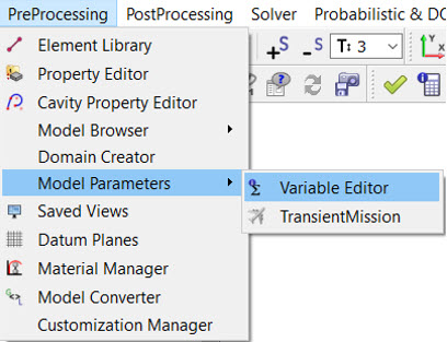
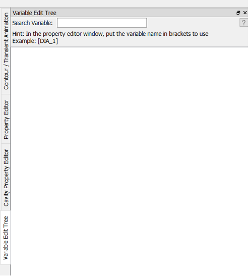
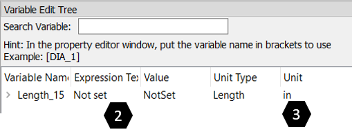
From the menu bar, select PreProcessing > Model Parameter > Variable Editor to access the Variable Edit Tree on the right side of the GUI. The Variable Edit Tree window lists the created variables.

Figure 1.
Figure 2.
In the graphic window of the Variable Edit Tree, right-click to create/add new variable. Enter the new variable name inside the variable edit pop-up dialog.
Note: If the entered variable name already exists, the following warning message is displayed:
Variable already exist make sure variable name is valid
.
After the new variable is created, it is added to the Variable Name list.
Figure 3.

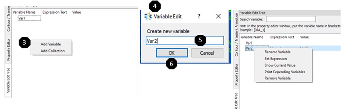
You can perform the following operations on a variable by right-clicking on the selected variable, and then left-click to populate the list of operations.

  1. Rename Variable: Rename the variable name if necessary.
  2. Set Expression: Widely-used option. It opens a separate GUI to define the expression based on the available result variable or the pre-existing variable. More information is available in the following section.
  3. Show Current Value: Evaluate and display the current value based on the defined expression.
  4. Print Depending Variable: Display dependent variables for checking purposes.
  5. Remove Variable: Remove/delete existing variables. Expressions associated with the variable are removed as well.
Another way to create a variable is to enter the variable, including the brackets [], in the Property Editor. The variable is automatically created with the correct unit type. Then, set the value for this variable in the variable editor. The Unit can also be changed.
Figure 4.


Figure 5.


You can assign units to each variable so the value is in the correct unit system. Prior to the 2022.1 release, the values had to be in English (“Flow Simulator”) units. You can assign each variable a Unit Type and a Unit. The Unit Type must match the unit type expected by the input that uses the variable. For instance, a tube element length input must use a variable that has the “Length" unit type. Then, from the drop-down menu, set the unit.
Figure 6.


Figure 7.


Figure 8.


A warning message is displayed if there is a mismatch between the unit type and the input. For example, in the figure below, you cannot use a variable with unit type = diameter as a pressure input.
Figure 9.


Working with Expressions

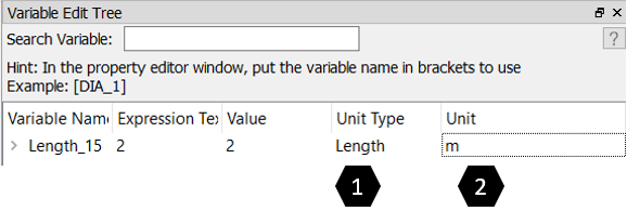
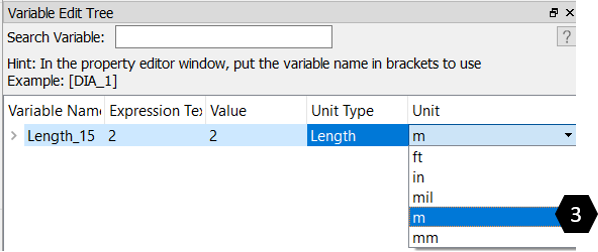
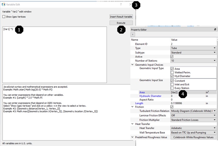
This section will provide more details on how to define expression. User can populate “Variable Edit” secondary window by selecting a variable inside “Variable Edit Tree” and right click and choose “Set Expression”. User can define the math expression based on JavaScript syntax. In the below example “Var2” is defined as a function of “Var1” (Var2 = 2 * Var1). After defining the expression inside the box, it is mandatory to click “Execute” button to be set it properly, otherwise the defined expression will not be evaluated. Result variable can also be used to define Variable by clicking “Insert Result Variable” button after completion of run for effective post-processing purposes. This option will be demonstrated in the Example Section.

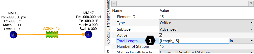
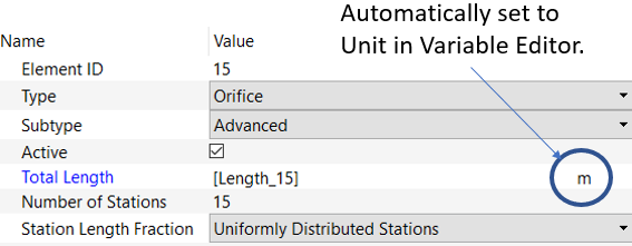
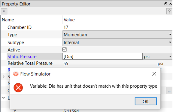
Once a variable is successfully created, it can be used as a value for a specific property (i.e. Area, Length etc) of an element/chamber as shown below.

Note: The independent variable name is inside a square bracket [].
Figure 10.

Refer Tutorial Exercise 18 : “Simple Tube + Orifice Element with Variable Definition” to understand the application of variable details.