Overview
GUI Overview
Flow Simulator interface is called as “FLODE” (Flow Design Environment) has a modern Qt/Qt-web based platform that provides
-
State of the art graphic user interface with the ability to overlay/integrate the 3D digital CAD with the analytical models
-
The GUI is geared for design where the Pre/Solver/and Post are all embedded in a single interface
-
Fully integrated optimization module provides the capability to quickly explore the entire design space within 3D modelling environment.
-
It is fully customizable that allows the user to modify how the GUI looks.
-
Users can import geometry information in the “.iges/.stp” form, as well as any image. This will help in visualizing the engineering problem in greater detail. It allows better 3D model building experience by mapping of elements & chambers to iges Vertices.
-
It also allows the user to import CAD in the “.iges/.stp” form & and creates elements automatically using all geometrical information of diameter, length, angle to updates input automatically.
-
Many wizards/options are available to aid users in model construction and simplification.
- Undo/Redo
- Model Checker to display warnings & Errors in the model
- Measure tool to measure Geometry information (Distance, Diameter, Area, etc.)
- Copy, Rotate, translate options to enable faster model building process.
- Merge different models in single database
- Compare two different models to identify differences in database
- Compare two different results files to quickly analyse the responses of modification in the inputs
-
The Unit Maintenance options allows the user to work on the unit system of their choice (British Units/ SI Units). The user is also given the option to create own set of units.
-
Sections of a model can be organized into Groups & Subgroups to improve usability of the model. Groups & Subgroups can be exported as standalone files.
-
Create scripts for controlling components or networks
-
Predefined library of elements which includes Orifices, Accumulators, all mechanical components (Bends, Tubes, Junctions), Pumps, Compressors, Valves, Heat exchangers, Controllers etc. with all the pressure & heat transfer characteristics associated with it.
-
Flow Simulator allows fully extensible platform provides customers the capability to integrate their own IP and element formulations seamlessly utilizing Python/Fortran scripting.
-
Flow Simulator contains lot of prepopulated materials and allows user defined materials that can handle mixtures based on NASA CEA libraries, handles spices transport & tracking, multiple fluids – Liquids & Gases.
-
Post Processing → Flow Simulator graphical interface enables viewing and manipulating of the data collected from the simulation. It contains the following functions and more:
- Graphically based data post-processing
- Quickly generate 2-D plots & Combine data from different cases, simulations, or tests into a single plot
-
Implicit links to ASCII/Excel files with database capabilities for fast and flexible access to measurement data.
- Import or Export data to/from MS/EXCEL files
- Perform various math operations on output data
- Contour / Transient Animation of transient processes
- User-definable tabular output of computed results
Panel Overview
Customizing GUI Looks
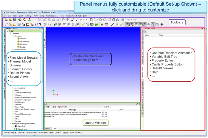
Flow Simulator allows the user to modify how the GUI looks. All menus contained under the Left or Right Panes, and Panes themselves can be moved or turned on/off. There are several options to this end:
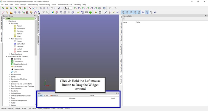
Example:1 By clicking and holding the left-mouse button and dragging the Info window towards the top of the screen as shown below:
Example:2 The Element Library is moved up to be the first menu of the Left Pane:
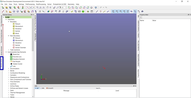
Example:3 The Property Editor can be moved to the top to give increase the area that he or she can use to visualize the model itself
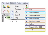
Another way to edit the GUI is to open the “Windows” menu and uncheck unwanted menus. For example, if the user does not wish to see the Variable Edit Tree, IGES List and the Cavity Property Editor, simply closing those Options would suffice. User can use View Menu to enable/disable toolbars & info/output/help tabs.