Use domain connectivity (discontinuous Galerkin domain decomposition method) to
connect a static mesh to a dynamic parameterised geometry without requiring node
connectivity. The parts may be separated by a small gap.
Note: Mesh connectivity between parts is achieved only when the parts have a common
interface with shared vertices (a continuous mesh).
A simulation model is often assembled from different parts. For example, a car model
meshed using Altair HyperWorks and imported into CADFEKO. An antenna geometry is then placed on the imported
mesh. To avoid re-meshing the full model to align the vertices on the common interface,
the domain connectivity approach can be used to connect the discontinuous mesh
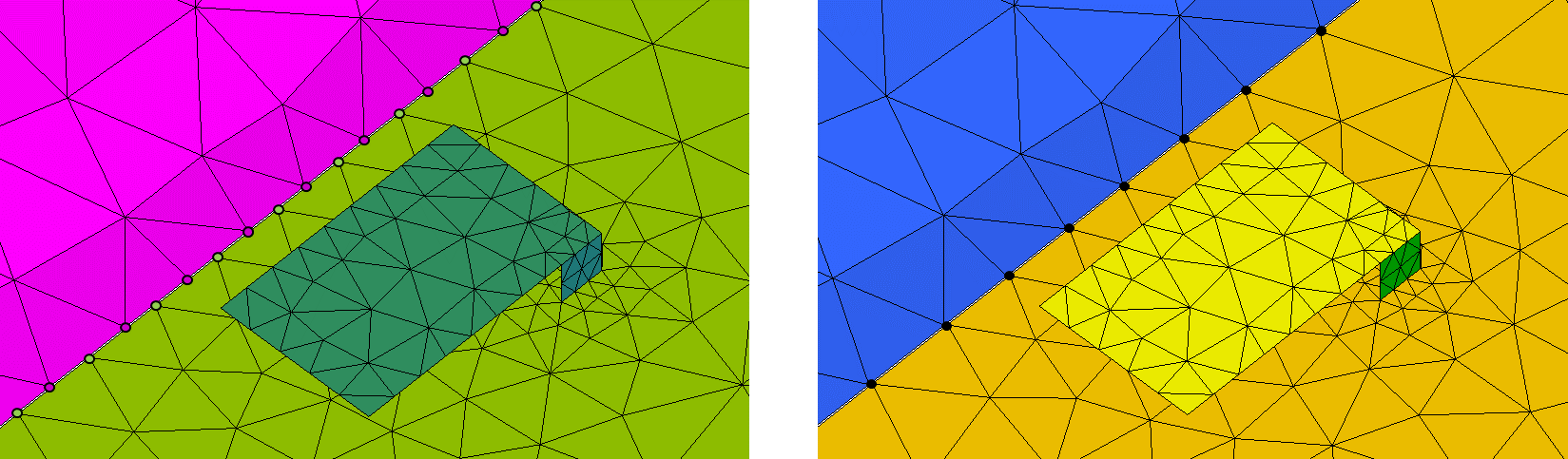
and geometry parts.Figure 1. Left: Mesh parts that have no mesh connectivity (triangles do not share
vertices on a common interface); Right: Mesh parts that have mesh
connectivity.
Apply the domain connectivity to discontinuous meshes where the gap between the meshes is
small in relation to the wavelength. For high accuracy, choose the gap distance
g as g = λ/ 1000.
Increasing the gap distance, the result becomes less accurate and margins
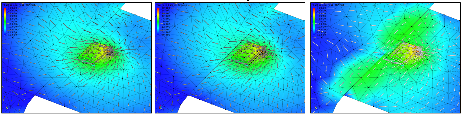
g > λ /100 should be avoided.Figure 2. Left: Mesh parts that have mesh connectivity; Center: Mesh parts that do not
have mesh connectivity but have domain connectivity defined; Right: Mesh parts
that have no mesh connectivity.