Creating the Model

Create the model in CADFEKO. Define any ports and sources required for the model. Specify the operating frequency or frequency range for the model.

  1. Create a dielectric medium.
    • Label: RogersDuroid5870
    • Relative permittivity: 2.2
    • Dielectric loss tangent: 0.0012
  2. Add a planar multilayer substrate (infinite plane) with a conducting layer at the bottom.
    1. Select Plane / Ground.
      • Click Planar multilayer substrate.
      • Thickness (Layer 1): 2.5e-3
      • Medium (Layer 1): RogersDuroid5870
      • Ground plane (Layer 1): PEC
      • Z value at the top of layer 1: 0
  3. Create the patch.
    1. Create a rectangle.
      • Definition method: Base centre, width, depth
      • Base centre (C): (0, 0, 0)
      • Width (W): 39e-3
      • Depth (D): 39e-3
  4. Create the inset feeds.
    1. Create a rectangle.
      • Definition method: Base corner, width, depth
      • Base centre (C): (-1.4e-3, -39e-3/2, 0)
      • Width (W): 2.8e-3
      • Depth (D): 6.5e-3
      • Label: InsetRectangleLarge
    2. Create another rectangle.
      • Definition method: Base corner, width, depth
      • Base centre (C): (-1.4e-3/2, -39e-3/2, 0)
      • Width (W): 1.4e-3
      • Depth (D): 6.5e-3
      • Label: InsetRectangleSmall
    3. Select InsetRectangleSmall and InsetRectangleLarge in the tree.
    4. Copy and rotate InsetRectangleSmall and InsetRectangleLarge by 90 degrees.
    5. Select InsetRectangleLarge and InsetRectangleLarge_1 in the tree.
    6. Subtract InsetRectangleLarge and InsetRectangleLarge_1 from Rectangle1 (target).


    Figure 1. Construction of the inset feeds for the patch
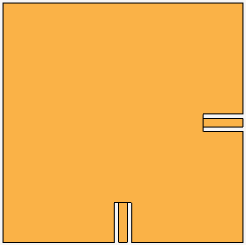
  5. Create two microstrip ports on the outer edges of the inset feeds, one port for each feed.
  6. Union all the parts in the tree.
  7. Create a new network.
    • Data type: S-matrix
    • Source: Touchstone file
    • Number of network terminals: 3
    • Browse for the .s3p file.
  8. Connect the input ports of the patch to the output ports of the network in the schematic view.


Figure 2. Schematic view showing the port connections.

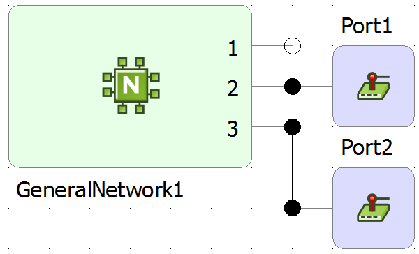
  1. Add a voltage source to GeneralNetwork1.Port1
    Note: The voltage source will not be displayed in the schematic view.
  2. Set the frequency.
    • Continuous (interpolated) range
    • Start frequency (Hz): 0.8*2.4e9
    • End frequency (Hz): 1.2*2.4e9
    Note: No output requests are necessary. The intput impedance of the voltage source is computed automatically.