Viewing the Results
View and post-process the results from the characterised surface in POSTFEKO.
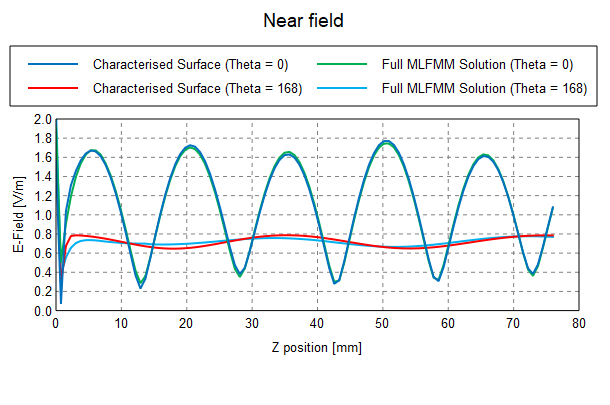
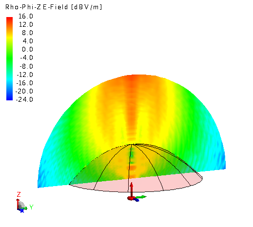
View the E-field above the characterised surface on a Cartesian graph. The results are compared to those calculated
with a full solution using MLFMM where the
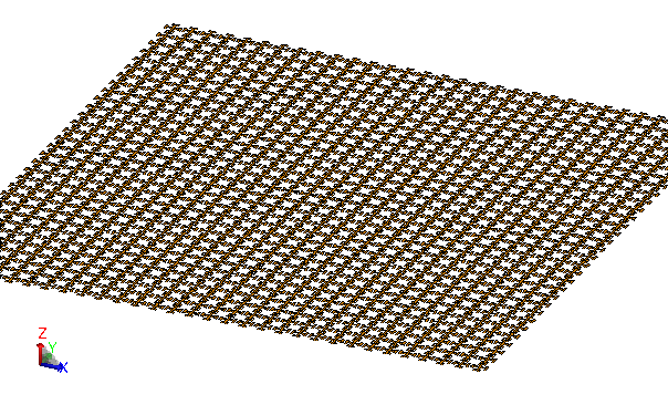
geometry of the FSS element was duplicated to
create the finite 31x31 element sheet.
| 31x31 FSS element sheet | Memory | Run time |
|---|---|---|
| Characterised surface - RL-GO | 91 MB | 9 sec |
| Full solution - MLFMM | 332 MB | 408 sec |
Note the significant reduction in computational requirements over the MLFMM solution.
A practical example where the characterised surface is extremely useful is shown below: an FSS nosecone radome is represented using this feature. Due to the size and complexity of the structure, it becomes prohibitive to model and solve with a full wave solution. However it can be solved readily with the characterised surface approach.