In multiple areas of WA, the parts of the products that
exist in the database are displayed in the Grid View.
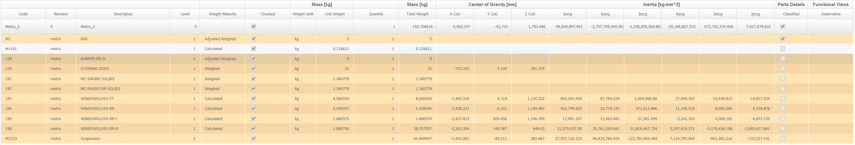
An example of the grid view is shown in the following image:
The following table displays the parts and all their attributes in the Grid View along with
the attribute definitions.
Table 1. The Grid View Attributes Table
Attribute Name
Definition / Meaning
Remarks
Code
Indicates the code name assigned to the part or assembly.
Revision
Indicates the Code and Revision together that form a unique identity of a part. The
part code is not changed once defined, but the revision number is changed by weight
engineers upon changes done to the parts.
Description
Indicates the text that describes the part.
For example: Frame at location 12432.
Level
Indicates the level of the part in the assembly hierarchy.
A 0 means the highest/root/product level. A level 1
part is the first sub-level below the top level product, a level 2 part is
the second sub-level below the top level product and so on.
Weight Maturity
Indicates the weight maturity of the part in the current snapshot.
The options are:
Adjusted Weighed
Weighed
Standard
Adjusted Calculated
Calculated
Estimated
Checked
Indicates that the part has been manually verified by a Weight Engineer and marked
accordingly.
Mass - Weight UoM
Indicates the unit of measurement used for Weight in the selected Program.
Mass - Unit Weight
Indicates the weight of a single unit of a part.
Quantity - UoM
Indicates the unit of measurement used to measure quantity of the part.
Quantity
Indicates the number of units of the part available in the product.
Mass - Total Weight
Indicates a calculated value. In case of assemblies the total weight is a roll-up of
the weight of the sub parts and assemblies.
Total Weight = Unit Weight x Quantity.
CoG UoM
Indicates the unit of measurement used to measure the Center of Gravity.
Center of Gravity - X CoG
Indicates the X coordinate of the Center of Gravity of the part.
Center of Gravity - Y CoG
Indicates the Y coordinate of the Center of Gravity of the part.
Center of Gravity - Z CoG
Indicates the Z coordinate of the Center of Gravity of the part.
Inertia UoM
Indicates the unit of measurement used to measure the Moment of Inertia of the
part.
Inertia - Ixxcg
Indicates the Moment of Inertia of the part about its principle X axis.
Inertia - Iyycg
Indicates the moment of Inertia of the part about its principle Y axis.
Inertia - Izzcg
Indicates the moment of Inertia of the part about its principle Z axis.
Inertia - Ixycg
Indicates the products of I along the X-Y plane.
Inertia - Ixzcg
Indicates the products of Inertia along the X-Z plane.
Inertia - Iyzcg
Indicates the products of Inertia along the Y-Z plane.
Part Details - Class
Indicates text fields where additional information about the part can be
specified as required.
Part Details - Material
Part Details - Process / Finish
Part Details - Supplier
Part Details - Design
Part Details - System
Part Details - Type
Part Details - Classified
Indicates if the part is a classified part.
Classified parts can be hidden from certain users based on the permissions assigned to
the user role.
Change Details - Change Reason
Indicates a pre-defined reason for changing the attributes or assembly structure of
the part.
The pre-defined options are:
Product Improvement/addition/ deletion
Product Configuration Change
Development Growth/Sizing Change
Supplier Growth/Request
Weight Improvement
Manufacturing Request
Rollback/Final Phase Request
Cost Savings
Regulatory Change
Safety Enhancement
Initial Load
Actual Weight Incorporation
Error Correction
Change Details - Change Detail
Indicates a text field for providing additional text related to the change.
Notes
Indicates a text field to add notes about the part.
Functional Views - US Code
Indicates the functional US Code for the part.
Functional Views - Automotive
Indicates the functional ATA100 code for the part.