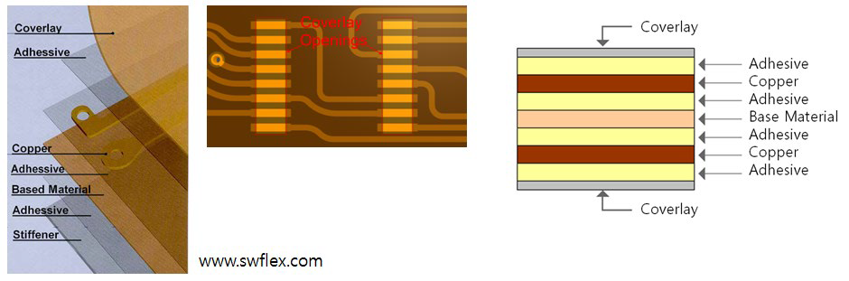
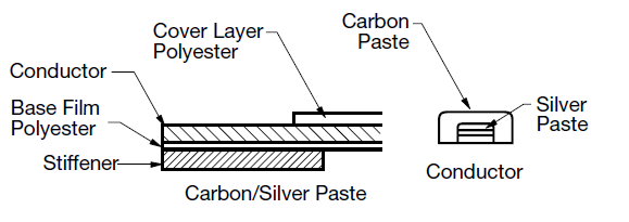
Components disposed on FPCB use the reinforcement plate, stiffener, in order to
compensate for the thickness of the component or to protect the component as safe in
SMT process.Figure 1. Figure 2.
Stiffener Layer Definition: Define stiffener layer for the top and bottom.
Stiffener Top Layer: Select stiffener top layer from the layer
list.
Stiffener Bottom Layer: Select stiffener bottom layer from the layer
list.
Component Selection: Select target components from the component
group list.
Exclude Components from Board’s Outline within given Distance:
Exclude components, placed near board outline. To select void
–checking component, set the distance between the component and
board outline.
Checking
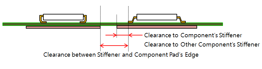
Clearance between Component Stiffener and Component’s Pad: Check the
clearance between the component stiffener and the component
pads.Figure 3.
Additional Void-Checking Component Selection: Add a new
additional void-checking component group by selecting a
component group from the list.
Clearance between Other Component Stiffener and Component’s Pad:
Check the clearance between the other component stiffener and
component pads.
Stiffener Existence at reverse Side of Target Component: Certain
components must have stiffener on the other side. Check the
existence of stiffener on the reverse side of target
components.
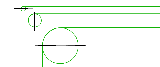
Check Stiffener’s Rounding in Corners: Check whether stiffener
corners are rounding. To check the sharp angle, use the radius in
the corner.Figure 4.
Minimum Radius for Stiffener’s Angle: Set the minimum radius
values.
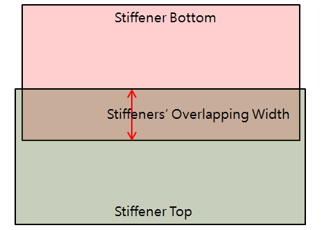
Minimum Overlapping Width between Top and Bottom Stiffener: If there
are top and bottom stiffeners in the same area, check the
overlapping width.Figure 5.
Checking for stiffener overlapping with component on same side:
Option to check whether the component is designed to overlap with
the Stiffener placement area.
Except component Group: Select a component group to exclude
from checking.
Clearance between stiffener edge and via: Clearance checking between
stiffener and via.
Check Uniform Pattern in both Side from Stiffener’s Edge: The
stiffener boundary is likely to be folded or bent due to the nature
of the FPCB. The possibility of breaking the routing increases if
the width of the routing becomes narrow or the angle of routing is
changed. This option extends the checking area from the outside of
the stiffener by the entered value.
Width: Check whether the width of the routing is changed in
the checking area.
Angle: Check whether the routing is bent in the checking
area.
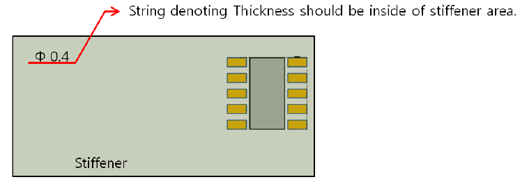
Check Existence of String for Stiffener’s Thickness: Check if there
is text string, denoting the thickness of a stiffener in the
stiffener area. The string should be matched with given thickness
value.Figure 6.
Define Top Placed Stiffener’s Thickness: Set the top
stiffener thickness value.
Define Bottom Placed Stiffener’s Thickness: Set the bottom
stiffener thickness value.
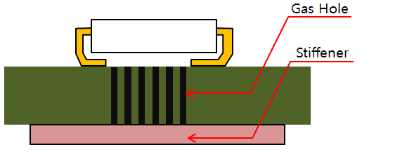
Gas Hole Stiffener: If there are gas-holes under components, you can
make rules for gas holes.Figure 7.
Gas Hole Layer Selection: Define the gas-hole layer by
selecting a layer from the layer list.
Minimum Gas Hole Size: Set minimum gas hole size.
Check Existence of Gas Hole in Stiffener: Check if there are
gas holes in stiffener area.
Clearance between Gas Hole and Stiffener: Set the clearance
value between gas hole and stiffener.