The 3-Phase Wound Field Synchronous Machines – Inner Salient Poles (Inner Rotor)
Motor Factory - The design
Introduction
- The “POLE” section is for designing the pole topology and dimensions.
- The “DAMPER” section is for defining the topology and dimensions of the dampers (bars and rings on both sides of the machine)
- The “WINDING” section is for defining the field winding architecture and the design of the associated coils.
 |
|
|
The 3-Phase Wound Field Synchronous Machines – Inner Salient Poles (Inner Rotor) The design environment in Motor Factory |
|
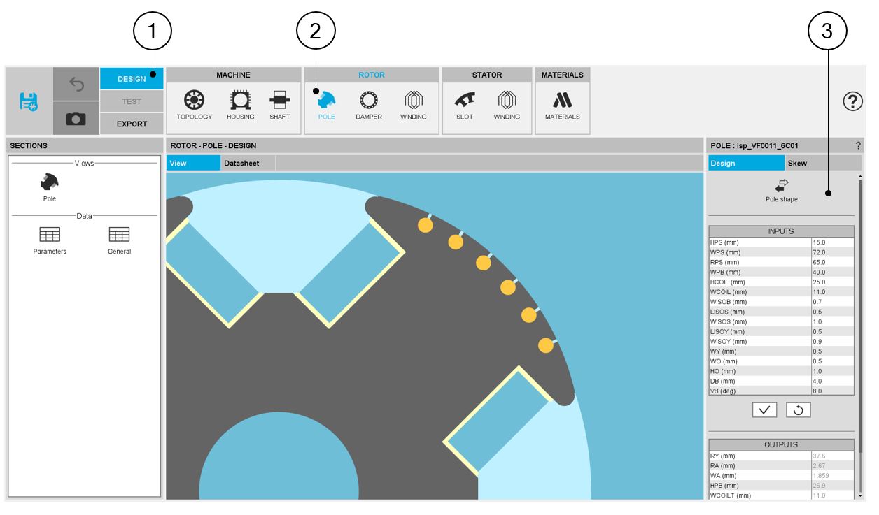
| 1 | The design environment |
| 2 | In the rotor area, three new sections are available: The POLE, the DAMPER, and the WINDING. |
| 3 | In the material section, the new active regions of the machine are considered. |
The Pole topology and dimensions
The section POLE is dedicated to the definition of the pole topology and dimensions.
 |
|
| The 3-Phase Wound Field Synchronous Machines - Topology and dimensions of the Inner Salient Poles | |
| 1 | The design environment. |
| 2 | Rotor area, the POLE section. |
| 3 | Inputs for defining the topology and the dimensions of the pole. |
 |
|
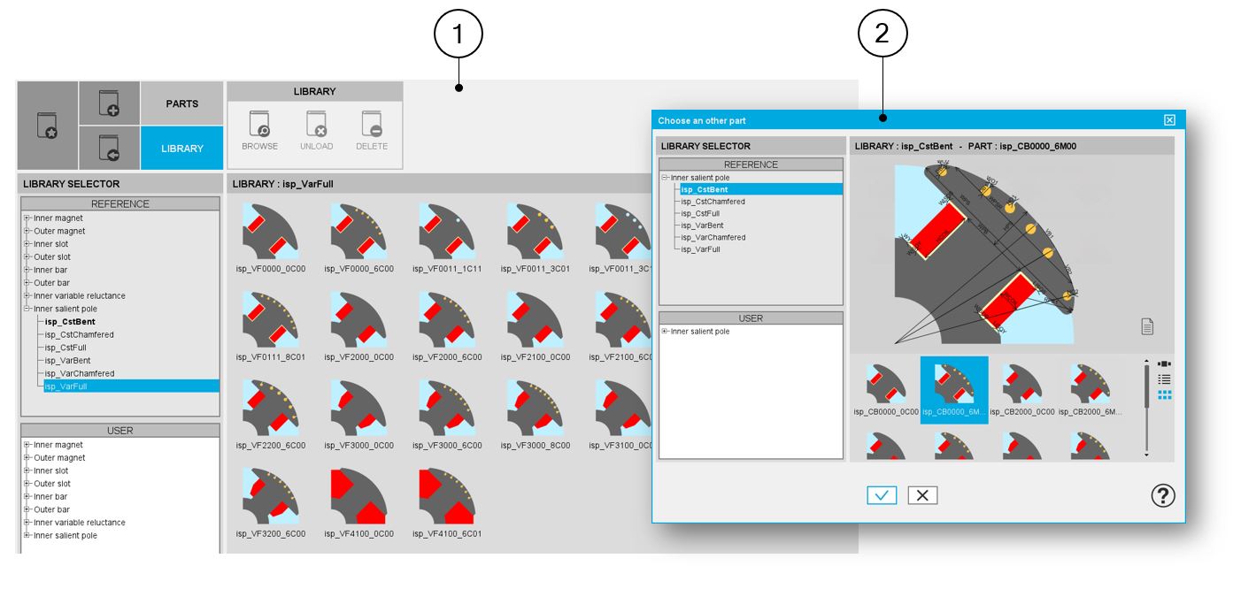
| The rotor Inner Salient Poles are available from the Part Library | |
| 1 | A lot of Inner Salient Pole topologies are available in Inner Salient Pole libraries. |
| 2 | The Inner Salient Poles can be selected in Motor Factory, among six libraries, to build the machine. |
The damper topology and dimensions
The section DAMPER is dedicated to the definition of the damper located in the "pole shoe". This allows us to define the end ring type (full ring or sector), the position, and the section of the rings on both sides of the machines.
The section scrolling bars allow you to define the characteristics of the damper needed to model them.
 |
|
| The 3-Phase Wound Field Synchronous Machines - Topology and dimensions of the damper end rings | |
| 1 | The design environment. |
| 2 | Rotor area, the DAMPER section. |
| 3 | Inputs for defining the topology and dimensions of the damper end rings. |
The field winding in the rotor
The section WINDING is dedicated to the definition of field winding.
The field winding architecture is used to build the rotor poles of the wound field synchronous machines.
For further information regarding basic knowledge and terminology about electrical winding, please refer to the user help guide: “Windings” which is dedicated to the winding design General user information.
The rotor field winding has a lot of similarities with the 3-phase winding. The section scrolling bars allow you to define the winding architecture, the characteristics of the coils, the insulation, and the end-winding dimensions. X-factors allow you to calibrate the field winding resistance if needed.
 |
|
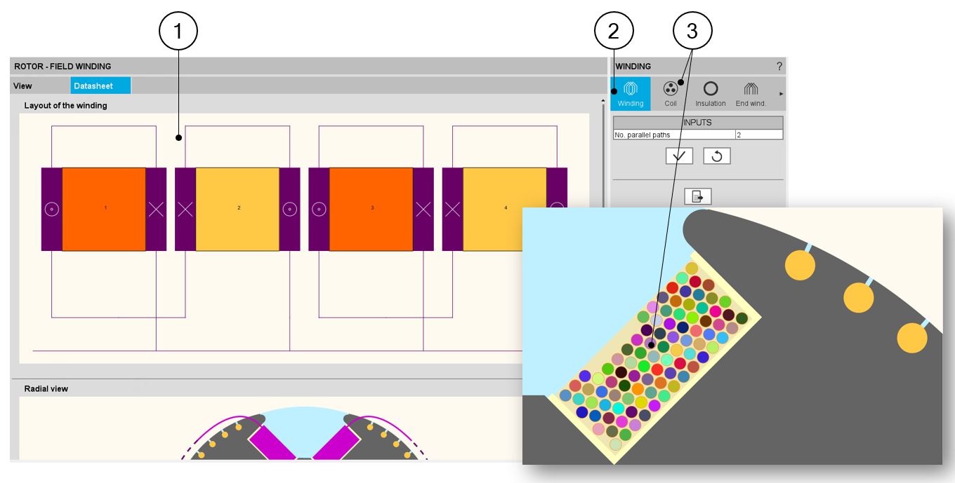
| The 3-Phase Wound Field Synchronous Machines – Field winding characteristics | |
| 1 | Field winding layout. |
| 2 | Winding architecture: how many parallel paths? |
| 3 | Characteristics of the coils: how is it wound? |
Motor Factory – Export area
- Export Documents
In the EXPORT area of Motor Factory, and like for all the machine types, it is possible to automatically build reports to describe all the work achieved for designing the machine’s topology.
At the same level, an export of a python script of a current motor in the application Script Factory can also be automatically generated.
- Export projects from FluxMotor® to Flux® 2D and Flux® Skew
On the other hand, once the design of the machine is achieved, it is possible to export their models in Flux 2D or Flux Skew for solving tests in magnetostatic or transient applications.
Then in Flux 2D or Flux Skew, tests like the computation of the back emf or the computation of a working point can be done.
 |
|
| The Wound Field Synchronous Machine with Inner Salient Poles (Inner Rotor) –The Export area in Motor Factory | |
| 1 | Export documents: The report |
| 2 | Export documents: The script |
| 3 | Export projects from FluxMotor® to Flux® 2D and Flux® Skew |
 |
|
|
The Wound Field Synchronous Machine with Inner Salient Poles (Inner Rotor). Export projects from FluxMotor® to Flux® 2D and Flux® Skew |
|
| 1 | In the Magneto Static application, one basic test for exporting to Flux® 2D (and Flux® Skew) is available. |
| 2 | In the Transient application, two tests for exporting are available: the working point and the back emf computations are available for exporting to Flux® 2D (and Flux® Skew). |
| 3 | While computing a working point, the main user’s inputs are the field current, the line current, the control angle and the speed. The temperatures of all the active regions like the windings and the dampers must be set. |
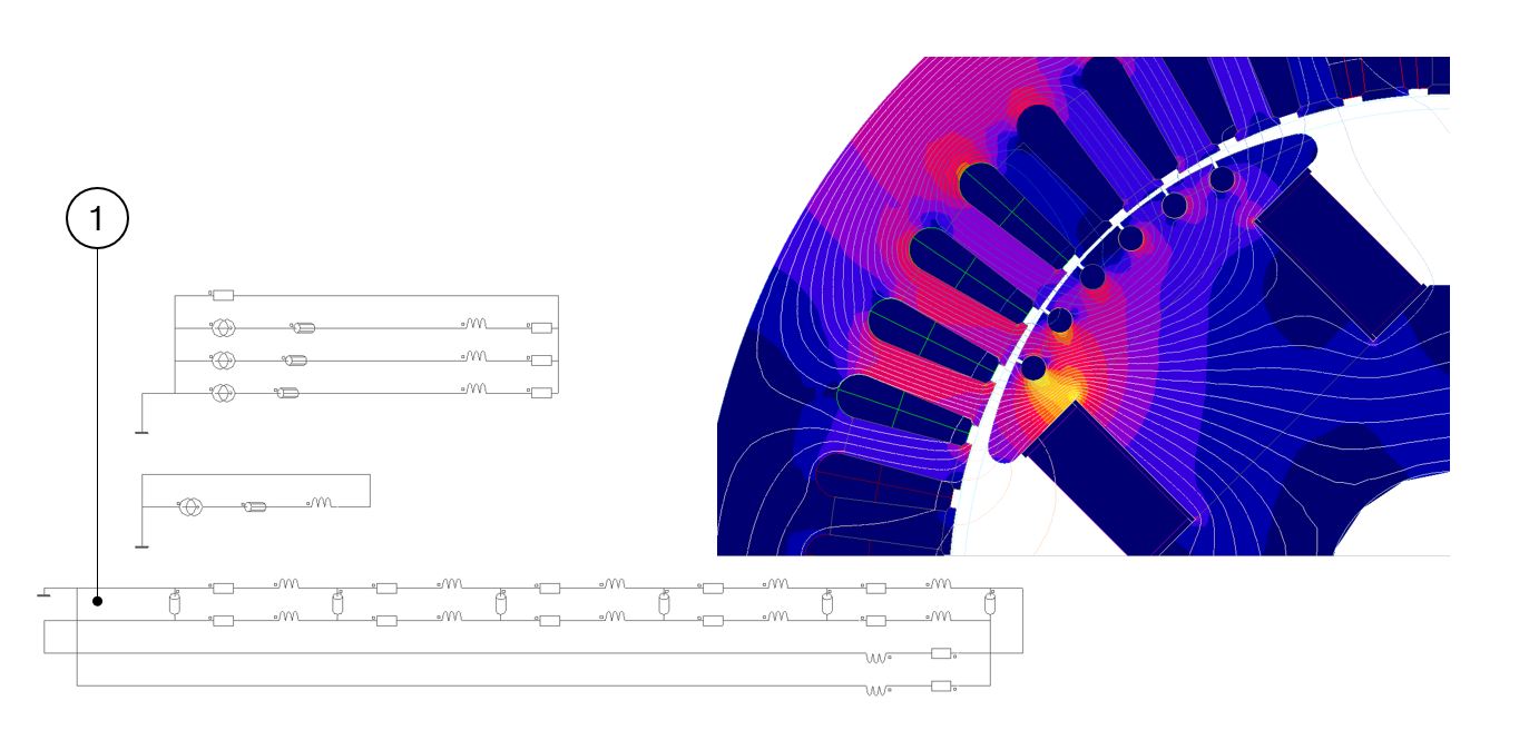
The electrical circuit is automatically done including the modeling of the dampers whatever is the considered configuration (number of poles, bars, …).
 |
|
|
The Wound Field Synchronous Machine with Inner Salient Poles (Inner Rotor). Electrical circuit and results |
|
| 1 | The building of the electrical circuit is automatically done, including the modeling of the dampers. |