Char. - Model - Motor - Scalar map
Positioning and objective
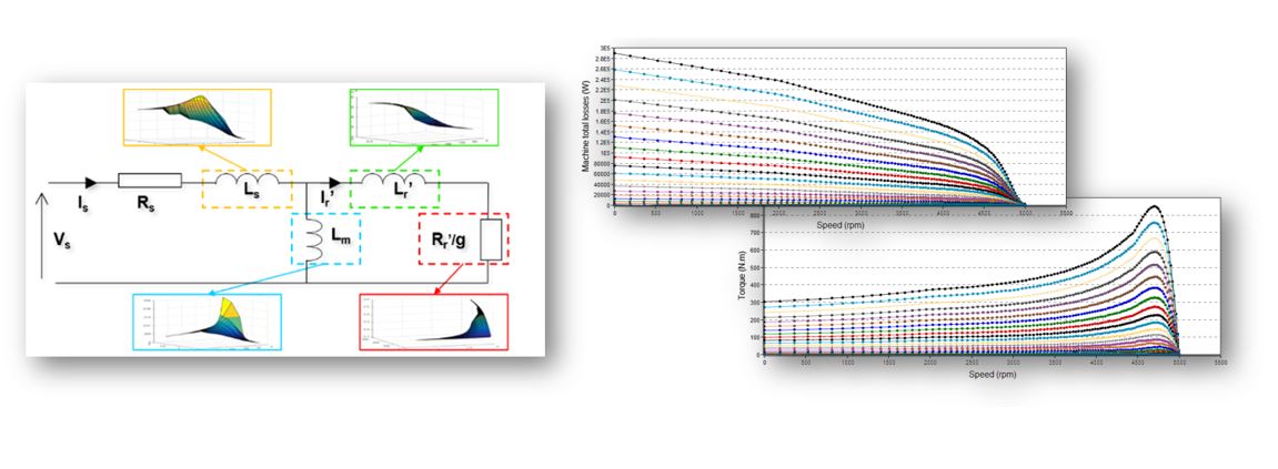 |
| “Characterization – Model – Motor – Scalar” Illustration |
The results of this test give an overview of the electromagnetic behavior of the machine considering its topology. For a set of Line-Line voltages (U) and a set of power supply frequencies (f), the general parameters of the machine like, mechanical torque, currents, power factor and power balance are computed and displayed as curves.
This gives the capability to make comparisons between the results obtained from the measurements and those with the Altair® FluxMotor®.
In this test, system engineers will find a characterization tool adapted to their needs and able to provide accurate curves ready to be used in system simulation software like, Activate or PSIM. Indeed, from results obtained in this test, a scalar drive and control can be applied.
The following table classifies the test “Characterization – Model – Motor – Scalar
| Family | Characterization |
| Package | Model |
| Convention | Motor |
| Test | Scalar |
| Positioning of the test "Characterization - Model - Motor - Scalar | |
User input
The four main user input parameters are the maximum Line-Line voltage, the Rated power supply frequency, the maximum line current and the maximum speed. In addition, the temperatures of winding and squirrel cage must be set in the power electronics, if needed.
Main outputs
- Mechanical torque
- Mechanical power
- Machine efficiency
- System efficiency
- Machine electrical power
- System electrical power
- Machine total losses
- System total losses
- Stator total losses
- Rotor total losses
- Mechanical total losses
- Power electronics losses
- Power factor
- Stator current