Introduction
1. Introduction
The dedicated test environment (TEST area inside Motor Factory) enables users to assess motor performance.
Standard and relevant test portfolios are available. All the predefined tests are ready to be performed.
Relevant input parameters allow users to control test conditions.
Processes are based on optimization technology. All the results are automatically illustrated.
Tests associated with the convention of operating Motor are grouped into packages and classified into test families.
| Test family | Topology | Package | Convention | Test |
| Characterization | IMSQ – IR/OR | Model | Motor | Basic |
| Characterization | IMSQ – IR/OR | Model | Motor | SSFR |
| Characterization | IMSQ – IR/OR | Model | Model | Scalar |
| Characterization | IMSQ – IR (1) | Thermal | Motor & Generator | Steady State |
| Working point | IMSQ – IR/OR (1) | Sine wave | Motor | U-f-N |
| Performance mapping | IMSQ – IR/OR | Sine wave | Motor | T(slip) |
| Performance mapping | IMSQ – IR/OR | Sine wave | Motor | EM Scalar |
| Mechanics | IMSQ – IR (1)(2) | NVH | Motor | Work. Pt. U-f-N |
| Mechanics | IMSQ – IR (1)(2) | NVH | Motor | Work. Pt. I-f-N |
| Mechanics | IMSQ – IR (1)(2) | NVH | Motor | Spectrogram - U-f-N |
| Mechanics | IMSQ – IR (1)(2) | NVH | Motor | Spectrogram - I-f-N |
-
The test (working point U-f-N, in motor mode is available for both topologies inner and outer rotor. However, the computation in steady state of the thermal behavior is available only for inner rotor topology.
NVH tests are also available only for inner rotor topology.
- In the current version, NVH tests are available only in beta mode user level (See user preferences – Advanced tab)
-
The tests are described in documents dedicated to each test family. Here is the list of available documents:
- MotorFactory_2026_IMSQ_IOR_3PH_Test_Characterization
- MotorFactory_2026_IMSQ_IOR_3PH_Test_WorkingPoint
- MotorFactory_2026_IMSQ_IOR_3PH_Test_PerformanceMapping
- MotorFactory_2026_IMSQ_IR_3PH_Test_Mechanics
2. Settings
Settings allow defining the context in which the test is going to be performed.
Their definition is specific to each test.
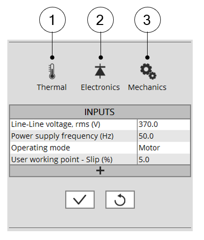
Settings are defined into three main domains:
- Thermal:
- To make the choice of the thermal solving (when available)
- To define the active components temperatures (Stator winding and squirrel cage)
- Electronics: To define the power electronics stage feeding the machine
- Mechanics: To define the mechanical loss model parameters
 |
|
| 1 | Button to define winding and squirrel cage temperatures to be considered in the test. |
| 2 | Button to define the user inputs of the power electronics stage |
| 3 | Button to define the parameters of the mechanical loss model |
Next sections of this document describe more in-depth of the available settings.
3. Advanced parameters
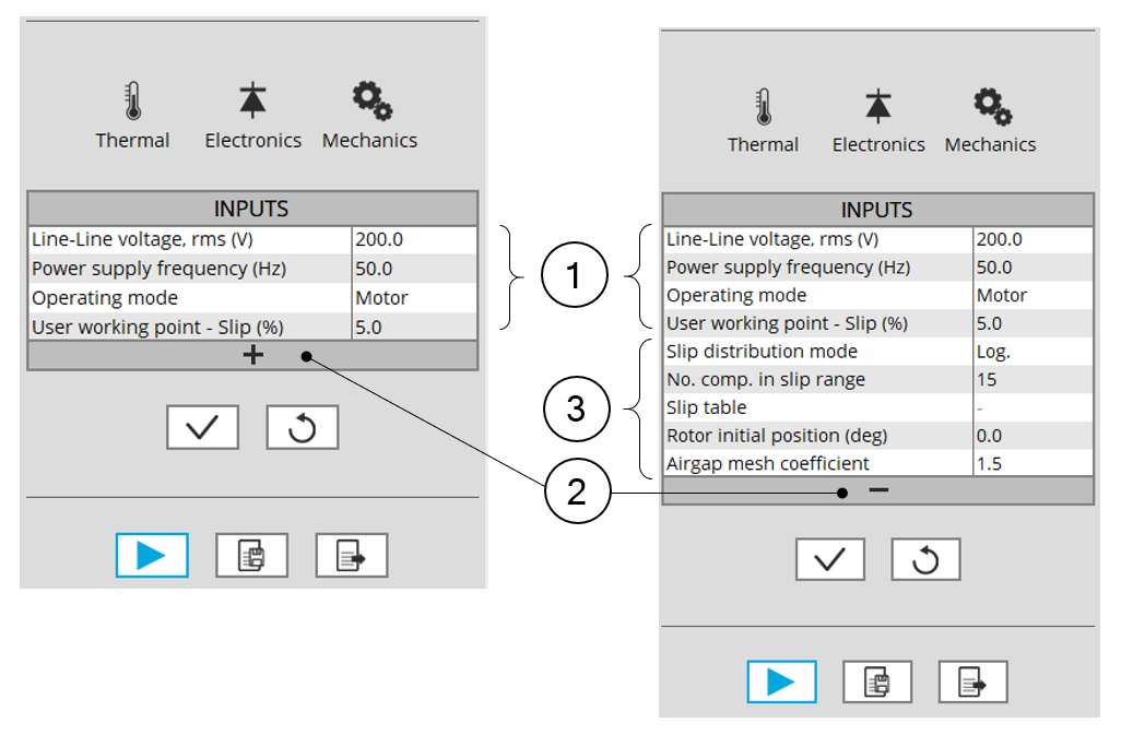
In addition to standard parameters, the users can access a list of advanced parameters.
Advanced parameters show additional parameters which helps in fine tuning of the computations in the software (through finite element modeling and simulation parameters) like the number of computations, Mesh order, Rotor initial position mode etc.
 |
|
| 1 | List of standard user input parameters |
| 2 | Click on “+” allows to display advanced parametersOnce displayed, advanced parameters can be hidden by clicking on “-” |
| 3 | List of advanced parameters |