System function
Introduction
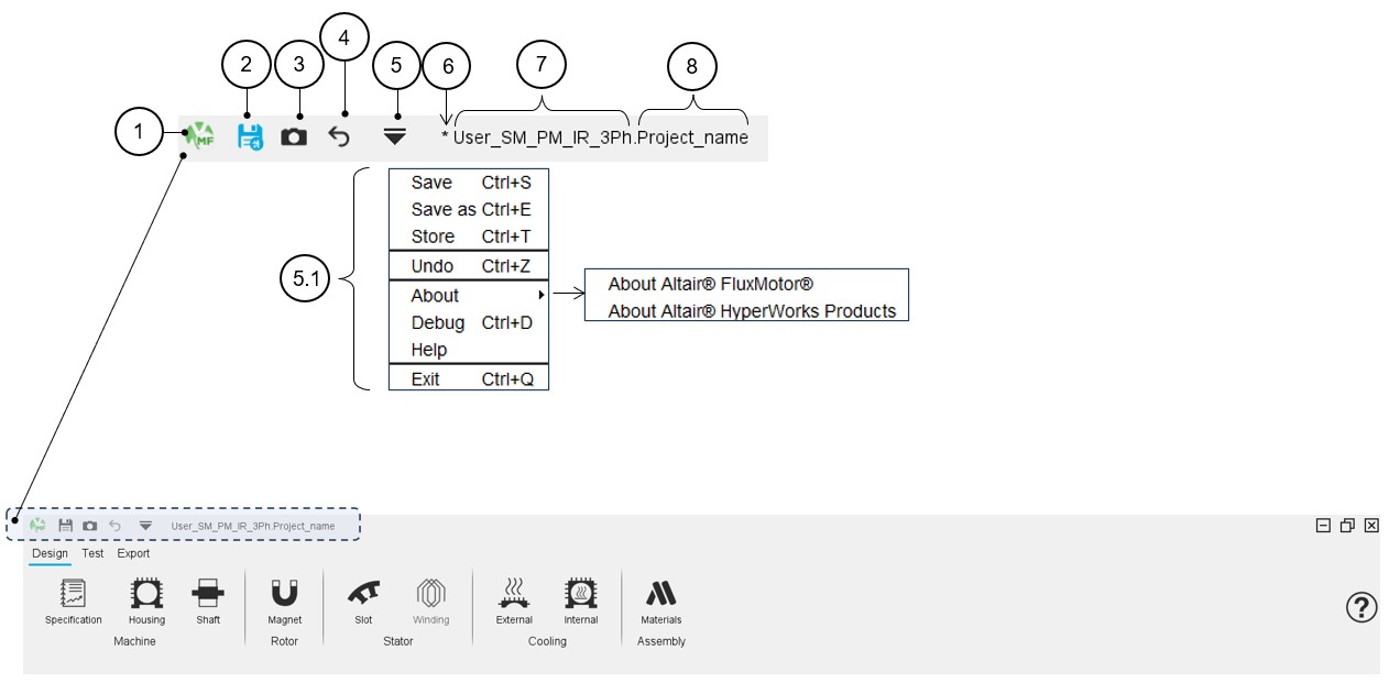
The main system functions are available from the icon bar located at the upper part of Motor Factory environments (Design, Test and Export).
 |
|
|---|---|
| 1 | Motor Factory logo = inactive icon. |
| 2 | “Save” a project is possible, directly from the top part of the
Motor Factory or via a dedicated icon that represents a floppy
disk. Note: The save function is also
available from the drop-down menu (5.1). |
| 3 | “Store” the project by clicking on an icon that represents a
Camera. Store a project allows the user to save the current motor in a file with a new name and then to continue the design on the current motor, which keeps its original name. Target: Store different steps of the design while continuing to work on the current project. Note: The store function is also
available from the drop-down menu (5.1). |
| 4 | Undo function cancels the last action. Note: The undo function is also available from the drop-down menu
(5.1). |
| 5 | Drop-down menu to access the main system functions. Note: Shortcuts to do the corresponding
functions are displayed next to the function
name. |
| 6 | The star symbol (*) indicates that the project is not saved with
the last modifications. Note: The floppy disk
remains blue as long as the project is not saved. |
| 7 | Name of the catalog in which the project (Motor) is stored. |
| 8 | Name of the motor. Note: The catalog name is
associated with the project name with a dot between them to
distinguish them. |
Project management
In this section we present how to save, how to save as, how to store the project, and how to Store the motor and continue.
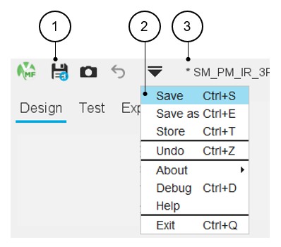
Save
 |
|
|---|---|
| 1 | “Save” a project is possible, directly from the top part of the
Motor Factory or via a dedicated icon that represents a floppy disk.
Note: The floppy disk remains blue till
the last modification has not been saved. Note: Access by using the shortcut CTRL+S
defined in the user preferences is also possible. Warning: A project cannot be saved
using the “Save” function until a name has been assigned to it
using the “Save as” function. |
| 2 | The save function is also available from the drop-down menu. |
| 3 | The star symbol (*) indicates that the project is not saved with the last modifications. |
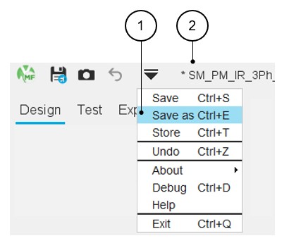
Save as
 |
|
|---|---|
| 1 |
“Save as” a project is possible only via the top drop-down menu. “Save as” a project allows to choose a new name for the project and save it in another catalog. The user must give a new name to the motor and select an existing catalog in which the motor will be stored. Note: Access by using the shortcut CTRL+E
defined in the user preferences is also possible.
|
| 2 | When a new project is created, before being “save as”, no default name is assigned to it, just the name of the default catalog and the star symbol (*) in front indicating that the project is not yet saved. |
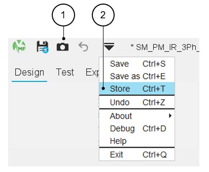
Store
 |
|
|---|---|
| 1 | “Store” a project is possible, directly from the top part of the Motor Factory or via a dedicated icon that represents a Camera. |
| 2 | The Store function is also available from the drop-down
menu. Note: Access by using the shortcut
CTRL+T defined in the user preferences is also
possible. Warning: A
project cannot be stored until a name has been assigned to it
using the “Save as” function. |
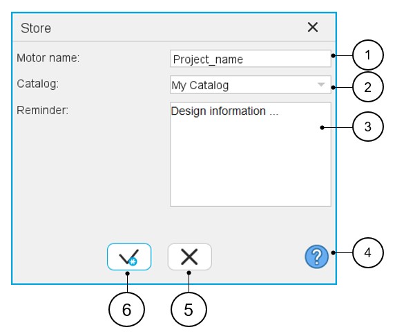 |
|
|---|---|
| 1 | Give a name to the project that corresponds to the design stage one wants to store. |
| 2 | Select an existing catalog in which the motor will be stored. |
| 3 | Memo to remind us of the main characteristics of the design one wants to store. |
| 4 | Access to the online user help guide, that corresponds to the dialog box of the function “Store”. |
| 5 | Button to cancel action and close the panel. |
| 6 | Button to apply inputs and close the panel. |
 |
|
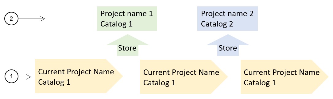
|---|---|
| 1 | The main design workflow is defined step by step. Some design stages can be "stored" during the design process to keep the main project variants and then to be able to recover and to compare them with the main workflow solution. |
| 2 | The “Store” function allows to store different design stages with a specific name and store them in a specific catalog. Hence, the user can continue the design work on the main design line. |
Store and continue
Once the design is done and at least one test is performed, it is not possible to modify the design without removing the test results.
If the user wants to keep the previous design and the associated test results, it is possible to store them.
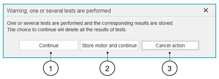
It is why, when the user attempts to modify the design of a machine (topology and / or dimensions) when there is at least one solved test result, a dialog box proposes three solutions illustrated below:
 |
|
|---|---|
| 1 | Continue = The test results are deleted, the modification
of the design is applied, and a new resolution is performed. Note: The project keeps its current
name. |
| 2 |
Store motor and continue = The current machine design with the corresponding test results is stored (= Function “store” is applied) in a new project - inside a selected catalog. The stored motor keeps the test results. The modification of the design is applied, and the new resolution
is performed.
Note: The current motor
loses the test results thus allowing the modification of the
design parameters. |
| 3 | Cancel = The modification of the design is cancelled. Previous modifications are cancelled. |
User actions
- Undo
Table 8. Undo function 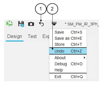
1 “Undo” last actions are possible directly from the top part of the Motor Factory or via a dedicated icon which represents a back arrow. The undo function cancels the last action. This action can be applied five times meaning that you cannot go back more than 5 actions.
Once a project is saved, the undo function becomes inactive (greyed icon) if no new modification has been made (Topology and / or dimension).
Note: Access by using the shortcut CTRL+Z defined in the user preferences is also possible.2 The undo function is also available from the drop-down menu. - About
Table 9. About function 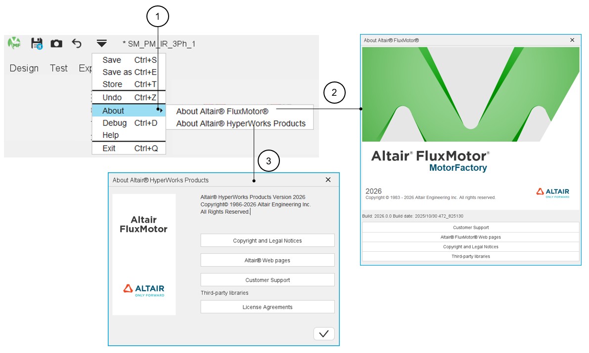
1 The “About” function gives access to additional information about FluxMotor or Altair® HyperWorks Products. 2 About FluxMotor gives access to: - The version reference number,
- Customer support information,
- FluxMotor webpages links,
- Copyright and Legal Notices,
- Third-party libraries.
3 About Altair® HyperWorks Products gives access to: - Copyright and Legal Notices,
- Altair® webpages links,
- Customer support information,
- License Agreements
- Debug mode function
The Debug mode function is dedicated to solving problems in the use of Motor Factory.
In case of trouble, instructions will be given by our support team to use this function.Table 10. Debug mode function 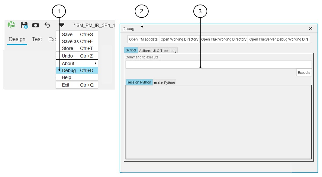
1 Access to the “Debug mode” from the top drop-down menu of Motor Factory. Note:Note: Access by using the shortcut CTRL+D defined in the user preferences is also possible.
2 Dialog box corresponding to the “Debug mode” function. 3 Window where the script functions can be run manually step by step. - Exit
Table 11. Exit – Close Motor Factory 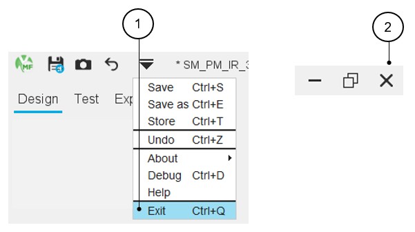
1 Close Motor Factory from the top drop-down menu of Motor Factory. Note: Access by using the shortcut CTRL+Q defined in the user preferences is also possible.2 Close Motor Factory by using the cross icon on the top right part of the Motor Factory panel. - Design inputs
In every section of the design there is an area dedicated to the user inputs. There are buttons that allow us to validate inputs or to restore default values.
Datasheets containing user inputs and the resulting data can be generated and exported as *.txt or *.xlsx files.Table 12. Motor Factory – Design – Management of user inputs 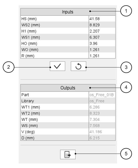
1 User inputs area. 2 Button to validate the inputs. Note: Pressing the “enter key” twice also applies inputs.3 Button to restore the default input values. This returns the input data to the reference state. 4 Output parameters (read only data) to complete the description of the topology. Note: The name of the part and its original library are mentioned in this section.5 Button to export datasheet into *.txt or *.xlsx files. Refer to the section “Export datasheet” for additional information.
Graphic management
- 3D view
Table 13. Motor Factory – Design – 3D view – Example of the synchronous machine with permanent magnets – Inner rotor 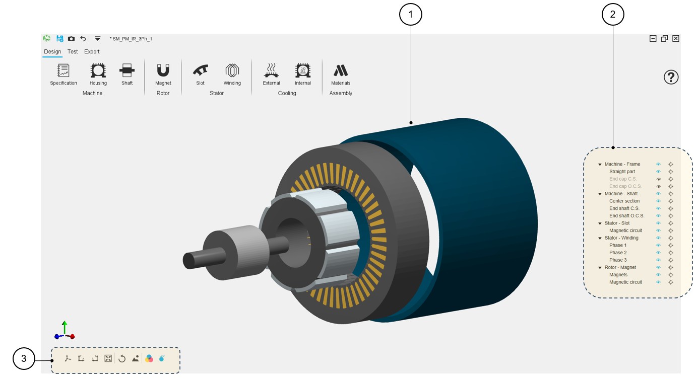
1 Displaying of the machine in 3D view. 2 Tools for visualizing or not machine regions. 3 Buttons to manage the 3D view displaying. Table 14. Motor Factory – Design – 3D view - Tools for visualizing or not machine regions – Example for a SMPM machine 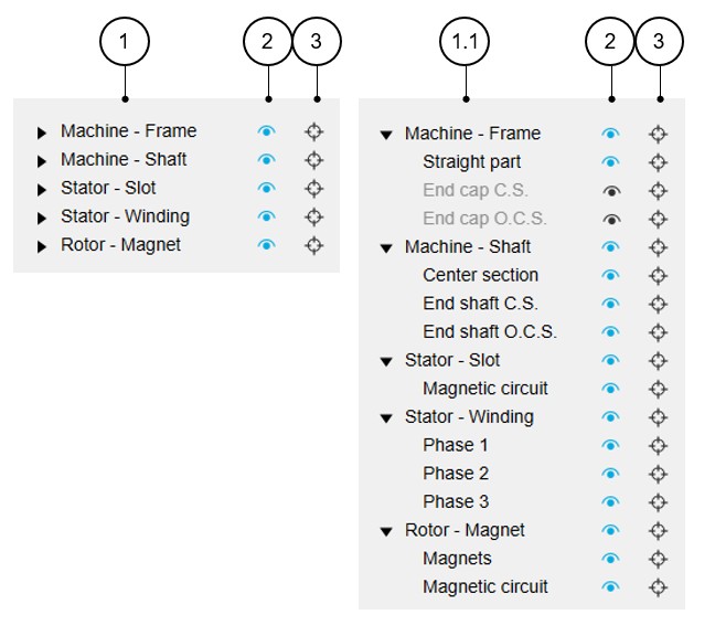
1 List of the main regions of the machine. 1.1 List of the main regions and the associated sub-regions of the machine. 2 The selector (eye) allows the considered machine region to be displayed (blue color) or not (black color). Note: When the selected “eye” is in front of a main region label, all the associated sub-regions are displayed.3 The selector (target) allows us to isolate the considered machine regions. Note: You can reset the 3D view to reinitialize the 3D view display and make all the regions reappear.Note: When the selected “target” is in front of a main region label, all the associated sub-regions are isolated.Table 15. Motor Factory – Design – 3D view - Buttons to manage the 3D view displaying – Example of a SMPM machine 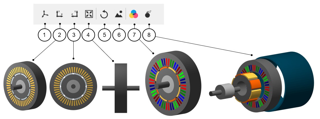
1 Displaying of the machine in 3D view = default 3D view. 2 2D view - Projection in the xOy plane. 3 2D view - Projection in the yOz plane. 4 Reset zoom. 5 Reset the 3D view display to come back to the default 3D view. 6 Export picture to *.png file. Note: Clicking on this button opens a dialog box to give a name to the exported non-vector (png) picture and a folder where to store it.7 Button to display or not the FluxMotor model colors (active regions), meaning the conventional colors used in FluxMotor to represent the winding phases. This allows us to well distinguish the phase order, for instance. The conventional magnet colors allow to well distinguish the north and south polarities.
Without this selection, the colors displayed represent a more realistic appearance of the different regions of the machine.
8 Button to display or not an exploded view of the machine. Note: A right-click allows us to access a list of the actions described above.Table 16. Motor Factory – Design – 3D view - Buttons to manage the 3D view displaying – Example of a SMPM machine 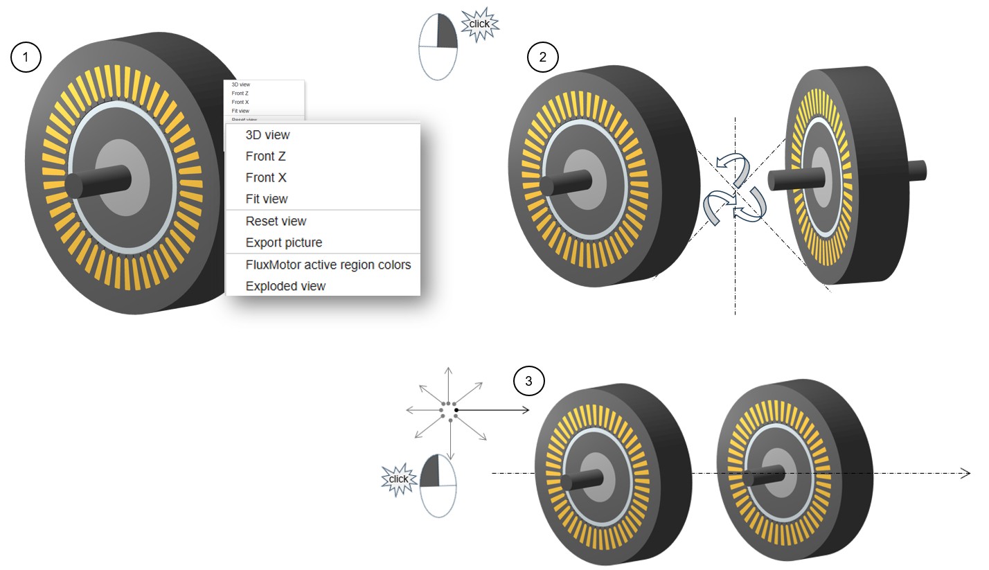
1 A right-click allows us to access a list of actions for managing the 3D view displaying. 2 Right click, and hold down on the image and drag to rotate the 3D view on all axes. 3 Left click, and hold down on the image and drag to move the 3D view in all directions. Note: At any time, reset the 3D view display to come back to the default 3D view. - Graphic functionsTwo graphic functions are available in every graphic area of the Motor Factory applications:
-
Reset zoom
This allows us getting back the original size of the picture (i.e. without zooming).
Reset zoom allows making the picture recover its original size.
-
Export a picture
Export function to get a picture with .png format.
The picture is captured by considering its original size (i.e. without zooming).
Figure 1. From any graphic window it is possible to access the graphic functions by using the right mouse button 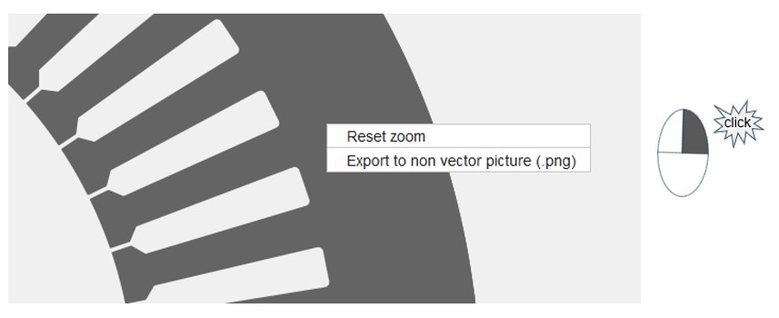
-
- Management of panels
When the computer screen is too small or when the resolution of the screen is too low, three buttons appear on the top part of Motor Factory panels. They are available to manage the displaying of panels in Motor Factory.
They allow us to remove or to display the right and/or left panels of the screen. See illustrations below.
Figure 2. Dedicated icons allow the management of panels in Motor Factory 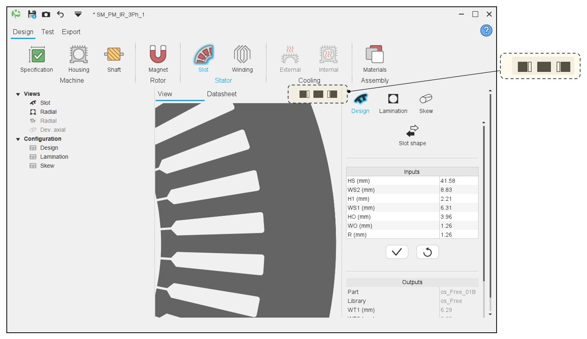
Table 17. Different ways to display (or remove) the panels in Motor Factory 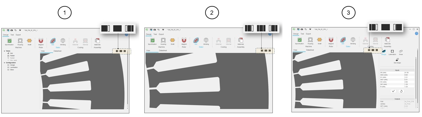
1 Right side removed and left side displayed. 2 Both sides (right and left) removed. 3 Right side displayed and left side removed.
Selection modes in GUI
- Section selection
Table 18. Scrolling selection bar – Example of the winding environment 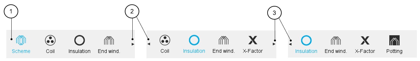
1 Scrolling selection bar where several sections can be selected. Section data can be reached thanks to shortcuts. 2 Arrows allow us to scroll the bar to reach other sections (on the right or the left) when needed. Note: When the number of available sections is less than or equal to 4, there is no need to display the arrows.3 The bar slides on the right to allow reaching the very last section available. Note:Such scrolling selection bars are implemented in every section of Motor Factory, whatever the environment is (Design, Test or Export).
Once one section is selected, the user inputs, the associated view and datasheet are displayed and ready to be used by the user.
- Multiple choices for inputs
A process allowing multiple choices for selecting the type of user’s inputs is implemented.
This allows us to give several choices within only one input line. Here is an illustration below that shows the different ways to define the electrical current in conductors.
Table 19. Multiple choice for inputs – Example for current and current density user inputs 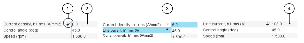
1 Icon allowing multiple choices to be given to the users. 2 First choice = Current density (A/mm²). 3 In that case two choices are possible: either the current density or the line current. Whatever the choice is, the units and the corresponding data are automatically updated.
4 Second choice = Line current, rms (A). - Auto / User switch
A process to switch between two types of answer (Auto or user, for example) is implemented.
For example, when the “Rotor initial position mode” is set to “Auto”, the initial position of the rotor is automatically defined by an internal process of FluxMotor®.
When the “Rotor initial position” is set to “User input” (i.e. toggle button on the right), the initial position of the rotor to be considered for computation must be set by the user in the field « Rotor initial position ».
Table 20. Auto/User mode switch – Example of application 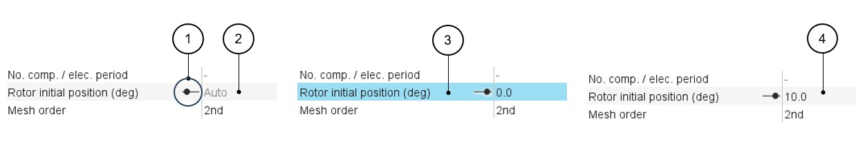
1 Icon to switch between two types of answer. 2 First position: automatic mode 3 Second position – The toggle button is on the right – One can write data in the field. 4 The toggle button is on the right side. The data is considered.
Warning messages
- Standard warnings
Table 21. Warning messages – How and where are they displayed? 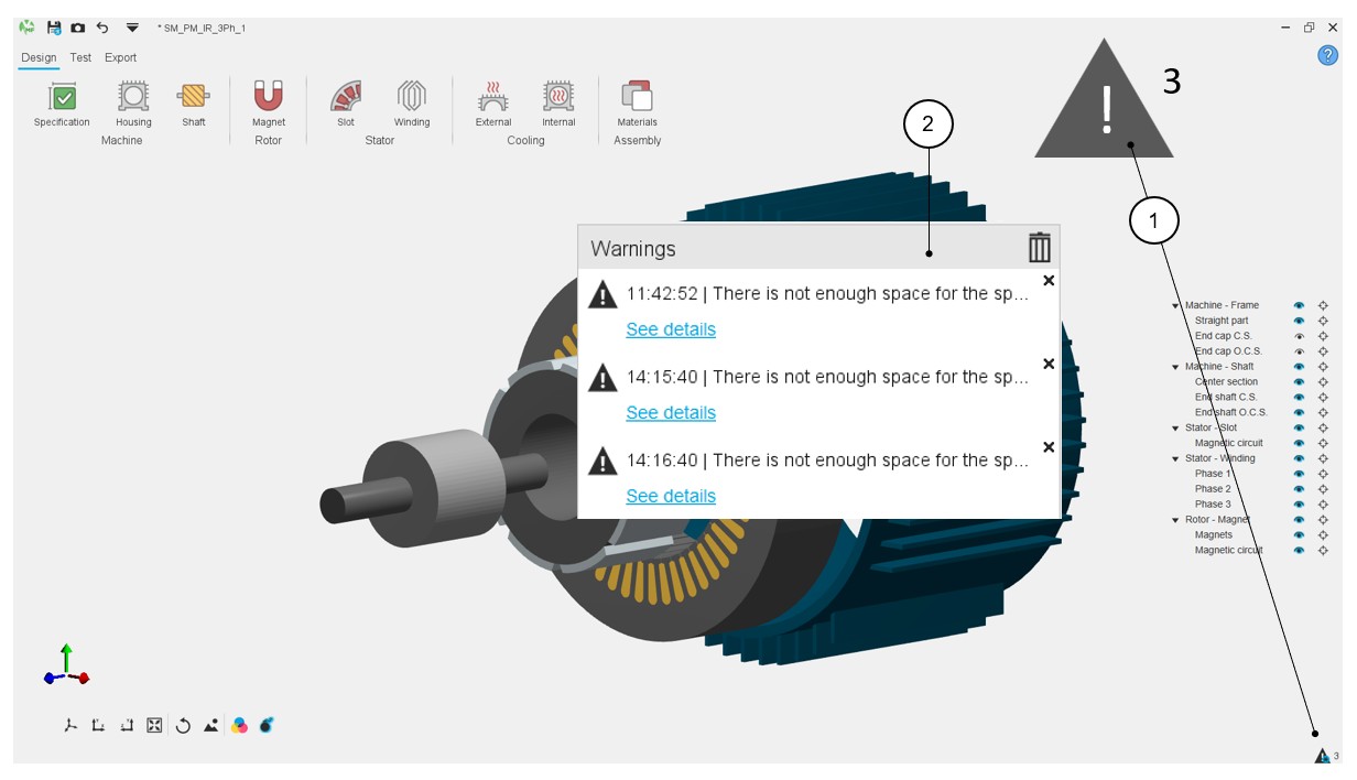
1 Location of the warning messages. The number (4 in the example) indicates the number of warning messages to read.
2 When the test is running or when designing a machine, messages can appear on the screen to notify the user about some warnings to check. Table 22. Warning messages – How to check them? 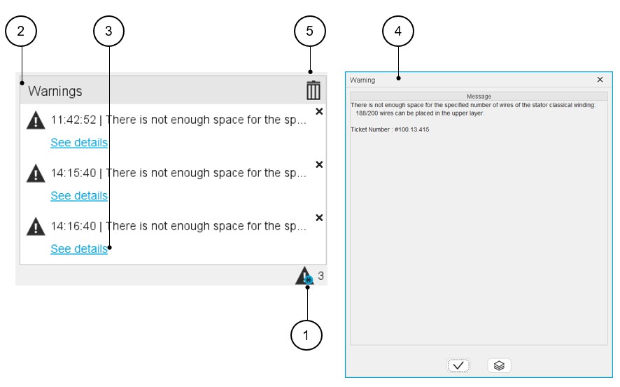
1 Click on the warning message icon to open the corresponding dialog box. 2 Dialog box dedicated to display warning messages. 3 Each warning message can be visualized by clicking on: “see details”. 4 Clicking on “See details” allows to read the warning message. 5 All the warning messages can be removed from the list by clicking on the bin icon. - Case of a design defectIn the Motor Factory Design environment, in the Stator section, buttons and winding icons can be colored red. This means that a design default must be corrected in the winding section of the design environment.
Table 23. Winding design issue 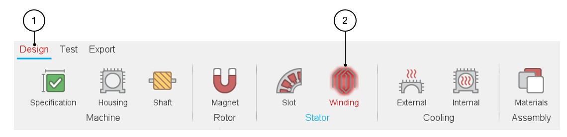
1-2 The design section and the winding icon are displayed in red color, meaning there is a design issue. Therefore, the tests cannot be performed. The tooltip message indicates that the slot filling is not valid, and the user must modify the slot filling parameters to unlock the test.
At the same time, a warning message indicates that there is not enough space for the specified number of wires. The allowed number of wires is mentioned in comparison with the targeted ones.
The tests cannot be performed. Export of project is not possible as well.Figure 3. The tests cannot be performed. Exporting project is not possible as well. The corresponding buttons are greyed and inactive.