Design area
Home page view
The description below is mainly based on one example dealing with synchronous machine with permanent magnets and inner rotor. However, the main principles are common for every kind of machine.
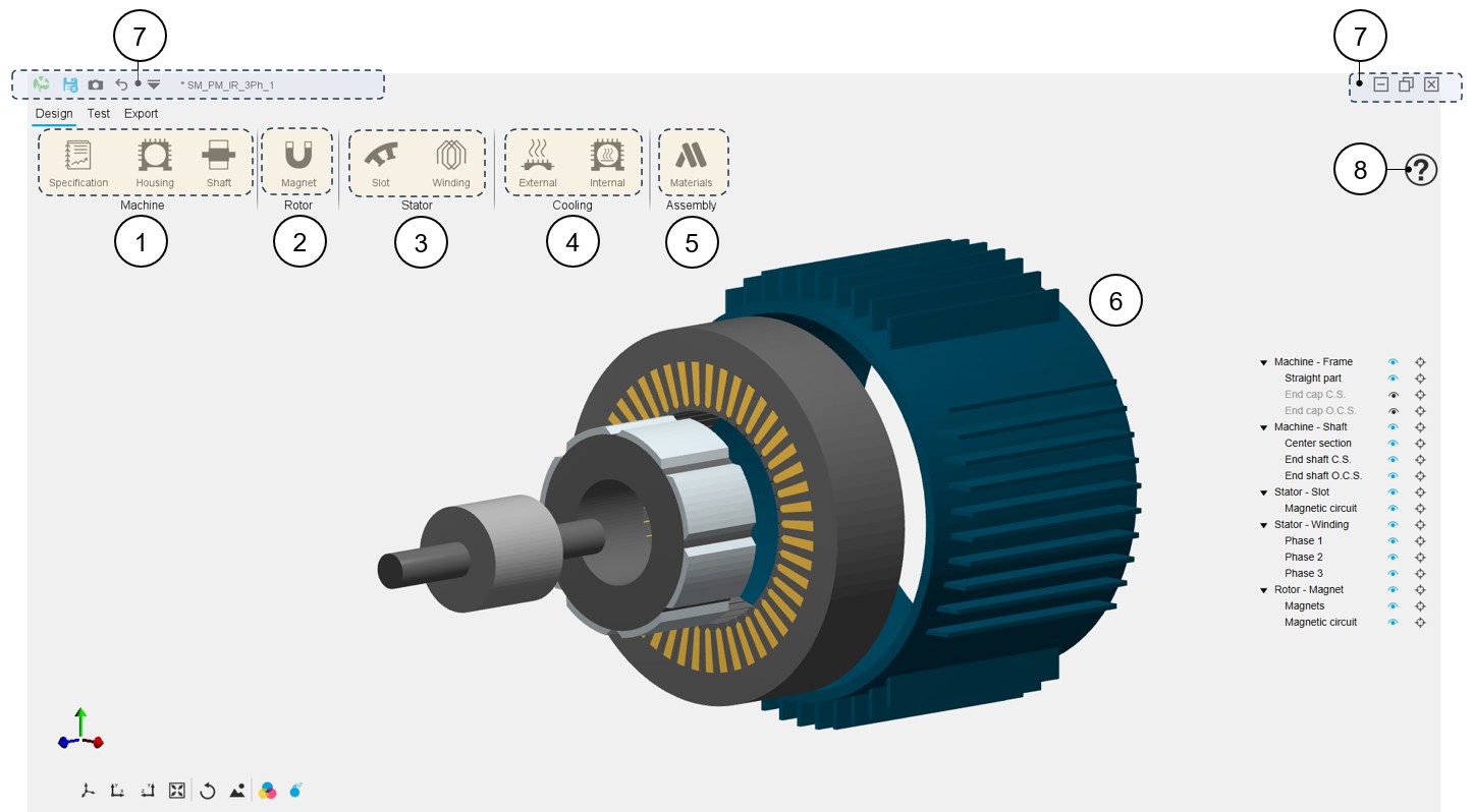
The aim of the GUI and workflow of the Motor Factory – Design area is to give a design guideline with a series of design cells to build the machine step by step. An overview of the Motor Factory – Design area is presented in the picture below.
 |
|
|---|---|
| 1 |
Machine section - Definition of general data of the
machine depending on the considered type of machine
|
| 2 | Rotor section - Access to the main functions to design the rotor and its corresponding subsets depending on the type of machine. |
| 3 | Stator section - Access to the main functions to design the Stator and its corresponding subsets depending on the type of machine. |
| 4 |
Cooling section – Definition of external and internal cooling parameters. Convection, radiation, conductivity parameters and X-factors
Note: By default, access to External cooling
and Internal cooling environments is locked.
Note: Some machine types have no
cooling devices like all the outer rotor machines. In such a
case, the external and internal cooling icons are greyed
whatever the housing and shaft status. |
| 5 | Assembly section - Area to select all the materials needed to build the machine, rotor, stator and the cooling and to define the stacking factor of both stator and rotor. |
| 6 | 3D view of the machine. Refer to the section dedicated to the management of this view in the section “System function – 3D view” |
| 7 | Access to general functions and tools for managing the project and the GUI. Refer to the section dedicated to the System functions. |
| 8 |
Access to the online user help guide dedicated to the
usage of Motor Factory – Design area.
Note: Each type of machine has its own dedicated online user help
guide. |
Design sections
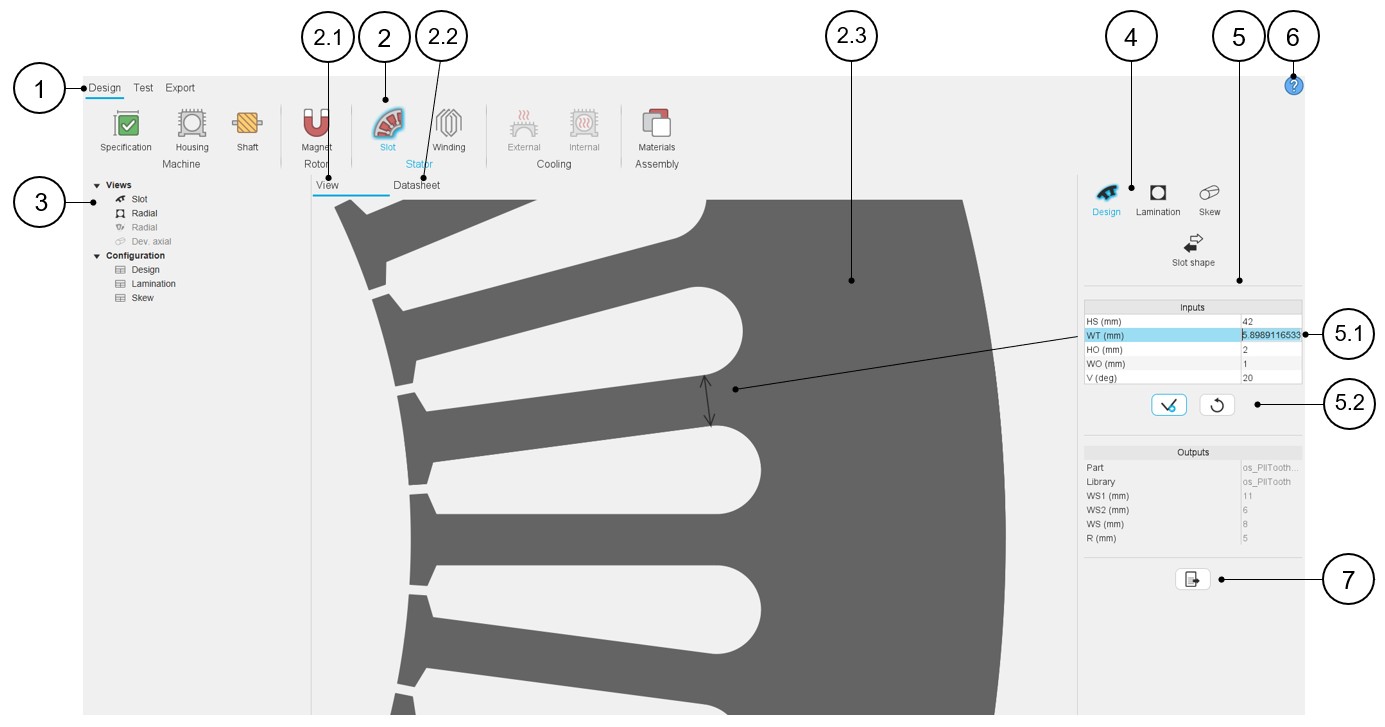
In Motor Factory design environment, several sections allow the design of the machine step by step. Each of these sections has the same presentation. The table below illustrates the different graphic tools allowing for good management of the design of the machine components.
 |
|
|---|---|
| 1 | In Motor Factory, selection of the design environment. |
| 2 | Icon to access the sub area (Slot area in this example) Note: A blue halo surrounds the selected
icon. |
| 2.1 | The default screen (View) allows displaying the main view, that illustrates the purpose of the study. |
| 2.2 | Each sub area has its own design report. It is visible under the tab “Datasheet”. This will be illustrated below. |
| 2.3 | Displaying the picture that illustrates the purpose of the study. |
| 3 | The selection tree where shortcuts allow reaching main sections of the current design report, is dedicated to the Datasheet. Clicking on a shortcut automatically focused on the selected item inside the datasheet. |
| 4 | Scrolling selection bar where several sections can be selected. Section data can be reached thanks to shortcuts.In this example three sections are available: Design, Lamination and Skew. Once one section is selected, the user inputs, the associated view and datasheet are displayed and ready to be used by the user. |
| 5 | Inputs are always displayed on the right part of the screen. |
| 5.1 | User inputs. When user inputs relate to topological dimensions, the relevant dimension is displayed on the graph with an arrow. |
| 5.2 | Button to apply inputs or to restore default values. |
| 6 | Access to the online user help guide dedicated to the selected
sub area (Slot in this example). Note: The
online user help guide is the same whatever is the considered
section (4) of the selected sub area (2). The sections are all
described inside of it. |
| 7 | Icon to export data into *.txt or *.xlsx files. |
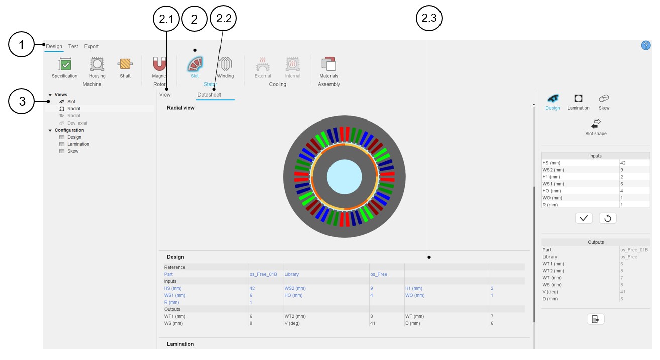
The next table described the tab “Datasheet”. The main functions described in the previous table dedicated to the main view are also available in the datasheet view.
 |
|
|---|---|
| 1 | In Motor Factory, selection of the design environment. |
| 2 | Icon to access the sub area (Slot area in this example) Note: A blue halo surrounds the selected
icon. |
| 2.1 | The default screen (View) allows displaying the main view, that illustrates the purpose of the study. |
| 2.2 | Each sub area has its own design report. It is visible under the tab “Datasheet”. This will be illustrated below. |
| 2.3 | Displaying the datasheet report which characterizes the purpose of the study with pictures and tables of data. In this table, data in blue corresponds to the row of user inputs and data in black corresponds to internal process computations. |
| 3 | The selection tree where shortcuts allow access to main sections of the current design report, is dedicated to the Datasheet. Clicking on a shortcut automatically focuses on the selected item inside the datasheet. |
How to choose part?
- Access to the Part Library
The “Part shape” button allows accessing the part libraries, from Motor Factory – Design area to change the part topology.
To illustrate the process to be applied for choosing a part, we are considering the example of a slot part since the workflow is the same whatever the considered part: Slot (inner or outer), Magnet (inner or outer), Saliency (inner), Bar (inner or outer), Pole (inner).
Figure 1. The “Part shape” button allows accessing the Part libraries - Case of the “Slot shape” (1) 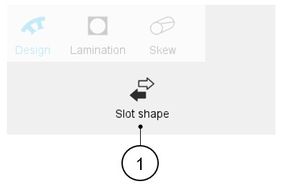
- Dialog box
- Main description
Clicking on the "Part shape" button opens a dialog box, allowing access to the corresponding Part Libraries.
It allows visualizing, comparing, choosing, and importing another part topology to modify the current stator design.
Table 4. Dialog box allowing to choose a part topology in Part Library 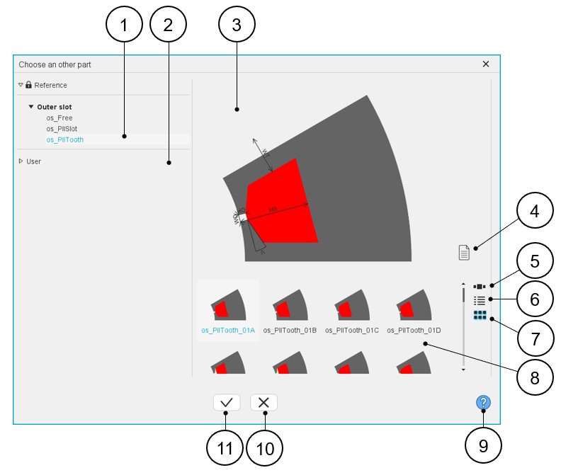
1 Visualization of the reference libraries, i.e., the libraries of topologies provided with FluxMotor. Select them to view their content and choose a part among them.
See the “Part Library” application for additional information.
2 Visualization of the user libraries. See the “Part Library” application for additional information. 3 Area where the selected part is displayed (static picture) – Topology + dimension labels. 4 Button to visualize the list of the attached documents. 5 Button to display the thumbnails as a slide show. 6 Button to display the thumbnails as a list. 7 Button to display the thumbnails as a matrix view of pictures. 8 Area to visualize all the topologies of slots from the selected library (ref. 1). 9 Access to the online user help guide dedicated to the usage of the dialog box. 10 Button to close the dialog box and to come back to Motor Factory – Design – Area dedicated to the considered part. 11 Button to choose and to import the selected part and to modify the current machine design. - Attached documentsIn Part Library, it is possible to attach files to the parts (or to the libraries as well). Hence, while choosing a part topology from the Motor Factory Design area via the dialog box described above, we can have access to these attached files if they have been stored previously.
Table 5. Visualization of attached documents 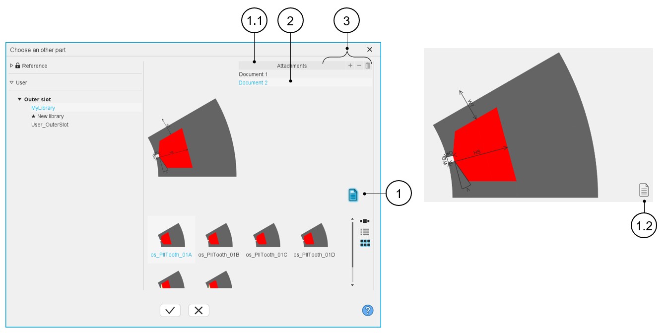
1 Button to show or hide the attached document list. Once clicked the button becomes blue and the attachments are displayed
1.1 Zone where the attachments are displayed after clicking on the button that manages attachments (1). 1.2 When the button that manages attachments is unclicked, it becomes black, and the attachments are hidden. 2 List of attached documents (if present). A double click on the selected document opens it. Documents can be added only from Part Library application. Refer to “Part Library” application for additional information.
3 Button (+) to add an attachment, Button (-) to remove one or several attachments and Button (Delete) for removing the selected attached file. Note: These buttons are greyed (not active) in the dialog box since attachments can only be managed in the Part Library.
- Main description
Thermal properties
By default, access to External cooling and Internal cooling environments is locked.
External cooling is unlocked when a circular or a square shape housing is defined (Machine / Housing / Design environment).
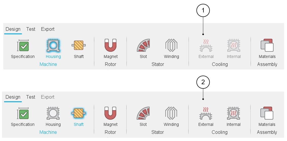
Internal cooling is unlocked when on the one hand a frame is defined (Machine / Housing / Design environment – circular or square shape) and on the other hand a shaft with bearings is defined (Machine / Shaft / Bearing environment). See the illustrations below.
 |
|
|---|---|
| 1 | External and internal cooling environments are locked. |
| 2 | External and internal cooling environments are unlocked. |
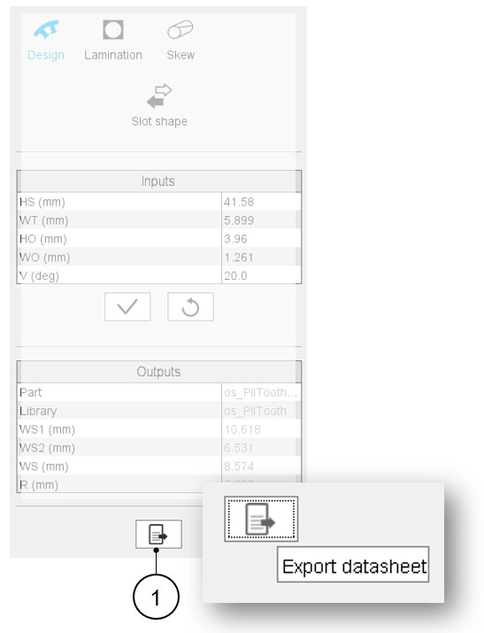
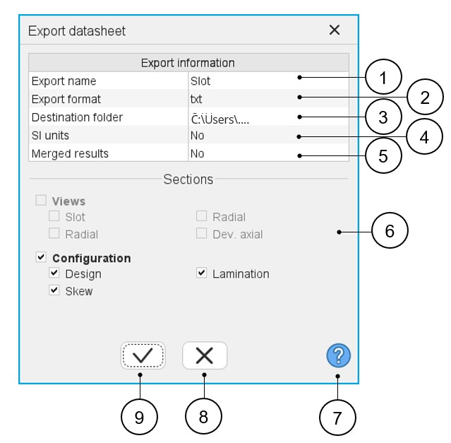
How to export datasheet?
In the Motor Factory – Design area, whatever is the considered context of design for the machine, rotor, stator, cooling or materials, it is possible to export data that define the design of the machine. In each context, on the bottom part of the user inputs, one finds a button (Export datasheet) that opens a dialog box that helps the user to select and to export datasheet in a *.txt or *.xlsx format.
 |
|
|---|---|
| 1 | Name of the exported text file. |
| 2 | Choice for exporting data into *.txt or *.xlsx files. |
| 3 | Folder in which the exported file will be stored. |
| 4 | System of units for numerical data can be given using SI Units
(Units based on International System of Units). When the answer is “No”, the default units used in FluxMotor are considered. |
| 5 | Merged results means the results are written in one text file.
When the answer is no, a text file is provided for each category
of result (Design, Lamination and Skew in our example). Note: When datasheet is exported in a *.xlsx
file, a tab is dedicated to each category of
result. |
| 6 | Visualization of all categories of results. Categories must be checked to add them to the selection of exported data. |
| 7 | Access to the online user help guide dedicated to the usage of the dialog box. |
| 8 | Button to cancel action and close the panel. |
| 9 | Button to apply inputs, close the panel and export the *.txt or *.xlsx file (in which the datasheet is stored. |