All machines
Layout of the winding – Winding connections
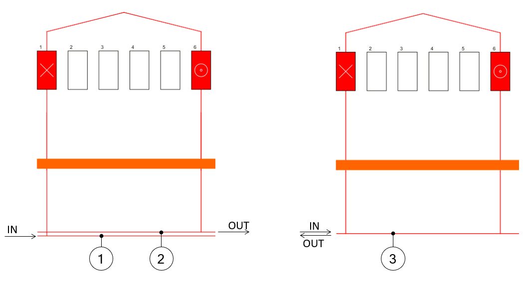
The representation of connections between coils and phases has been modified.
The lines that collect incoming and outgoing connections are merged into a single line. This has been done to make polyphase winding diagrams easier to read.
The picture below that illustrates the difference between the two representations.
 |
|
| Representation of the winding connections | |
| 1-2 | In previous versions, the two lines connection were represented. |
| 3 | In new versions, only one line corresponds to both IN and OUT connections |
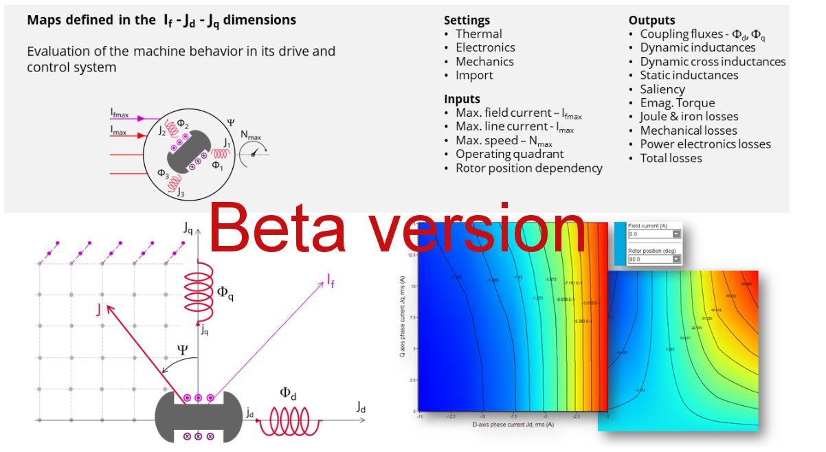
Features available in beta mode.
Sometimes, a new test is provided in beta mode, meaning that it is not entirely qualified. However, we make it available for testing, and we invite the users to give us their feedback and comments for improving this feature even more.
To indicate the “Beta mode” status of the test, “BETA VERSION” is written in the overview of the considered test as illustrated below.
Here is an overview of the test, as shown below.
 |
| Example of a test provided in beta mode |
Distribution of computations cannot be used for computing NVH spectrogram (FXM-15772).
Winding – Expert mode – defining of several circuit per sector.
In Expert mode, several parallel circuits can be defined in a sector and moreover several coils can be built in one circuit.
Such circuits can be connected in parallel according to the user’s input No. parallel paths.
In that case, it is mandatory to balance all the parallel paths well while building and connecting the coils inside all the circuits.
Natural convection for end winding
While choosing a model, where the end spaces are cooled with natural convection, the FluxMotor® model uses quite a low rotor tip speed ratio (a value of 5) to describe the fluid velocity far from the rotating components. This may lead to an overestimation of the cooling of the end winding on high-speed machines.
When a tip speed ratio of 5 seems to overestimate the end winding cooling, it is advised to switch to forced convection mode.
This mode allows forcing some higher tip speed ratios for areas far from the rotor, but reduces the efficiency of the cooling on the end winding.
This model will be improved for future versions.
Modification of units
To take the change of units into account in a test, the user must reopen Motor Factory. The modification is not considered instantaneous in applications of Altair FluxMotor® like Motor Factory.
Export a model into Flux® environment with represented elementary wires.
- Building time of the model in Flux®
When slots are filled out with a lot of elementary wires, and all the phases need to be represented with solid conductors inside the Flux® 2D model, the resulting python file can be very long. Therefore, the process of building the corresponding model in the Flux® environment can take a longer time.
Browse function
Sometimes, opening a folder from FluxMotor® applications via the browser function requires a longer time (several seconds).
Export environment – HyperStudy®
- Compatibility of HyperStudy connectors with respect of FluxMotor solver
versions
The process that describes how to update the HyperStudy connector is written in the user help guide “MotorFactory_2023.1_Introduction.pdf”
- New test and connectors for HyperStudy®
Connectors for coupling FluxMotor® and HyperStudy® are not yet available for the new added tests, like those with transient thermal computations or the tests for induction machine like the “Characterization – Model – Motor – Scalar” and the “Performance mapping – Sine wave – Motor – Efficiency map scalar”.
- Mandatory synchronization between connector and FluxMotor versions
The connectors used in HyperStudy must be synchronized with the FluxMotor solver version.
An error message (inside the log files) is generated while performing HyperStudy studies with a connector provided with a former version of the FluxMotor solver.
Problems with slot filling
- Slot filling is not yet possible with a non-symmetric parallel slot.
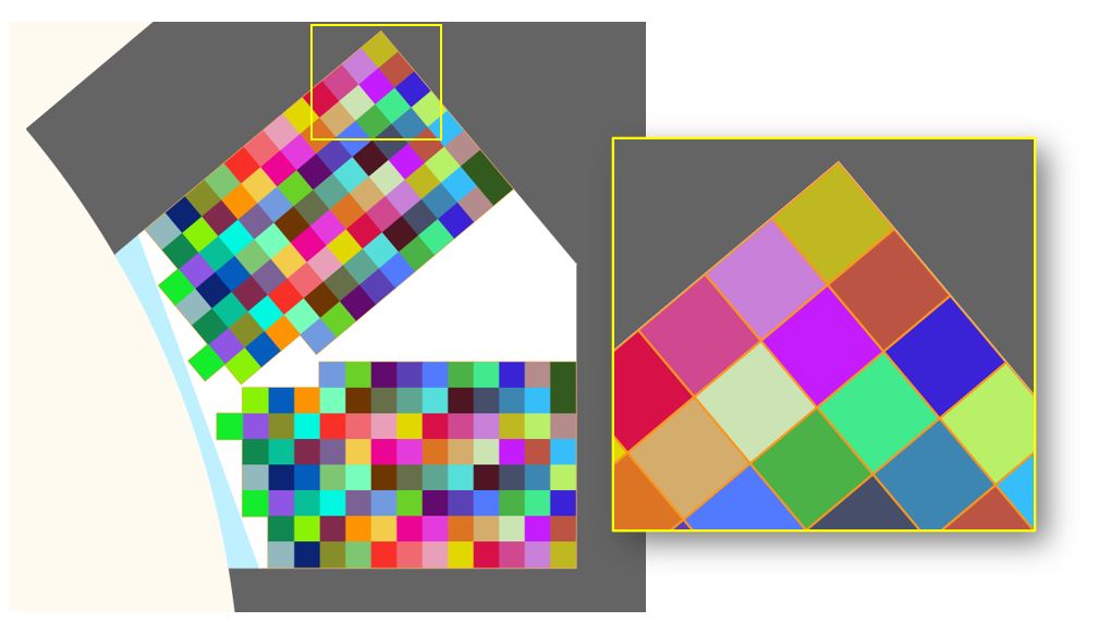
- When a toothed winding design is considered with rectangular shape wires, the
conductor grouping method "horizontal" doesn’t work properly, leading to the wrong
visualization of conductors. In that case, it is recommended to select the conductor
grouping method "vertical".
All work well with circular shaped wires.
Example with a toothed winding design (i.e., the coil pitch = 1) and with 2 wires in hand.
 |
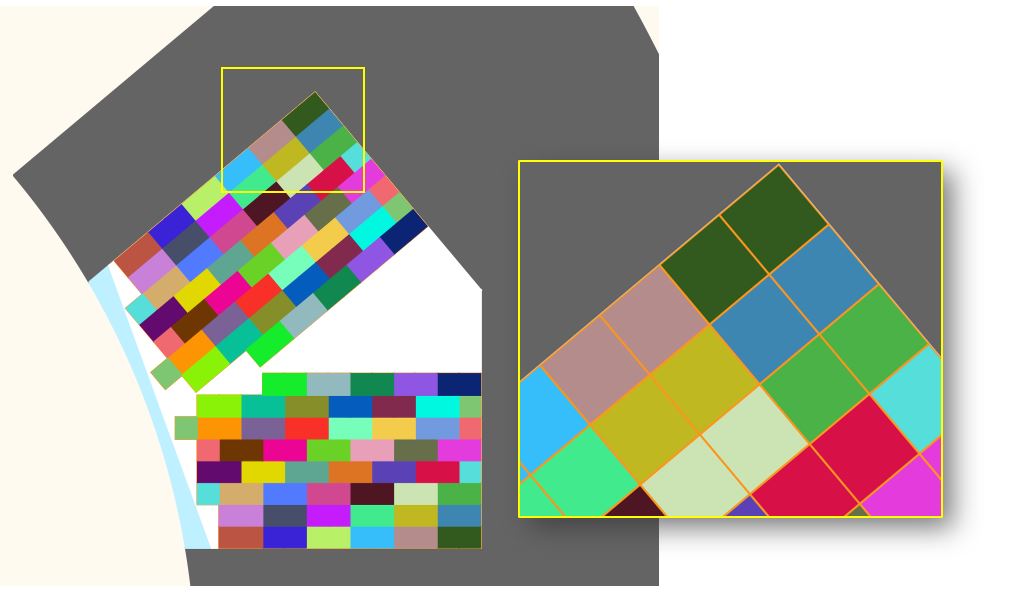 |
| Horizontal filling – wrong visualization, but the total number of wires is right | Vertical filling – good visualization |
NVH computations - Advice for use
The modal analysis and the radiation efficiency are based on analytical computation, where the stator of the machine is considered a vibrating cylinder.
The considered cylinder behavior is weighted by the additional masses, like the fins or the winding, and the subtractive masses, like the slots and the cooling circuit holes.
This assumption allows for a faster evaluation of the behavior of machine in connection to NVH. But in no way can this replace mechanical finite element modeling and simulation.
- The limits of the analytical model are reached or exceeded.
- Unusual topology and/or dimensions of the teeth/slots
- Complexity of the stator-frame structure when it is composed of several components, for instance.
- The ratio between the total length of the frame Lframe and the stack length of
the machine Lstk. In any case, this ratio must be lower than 1.5:
L_Frame/L_stk ≤1.5