Settings
1. Introduction
Three buttons give access to the following setting definition: Thermal, Electronics and Mechanics. Each kind of settings are shortly defined here-after.
Additional information can be read in the document: MotorFactory_2026_SMPM_IOR_3PH_Test_Introduction – sections dealing with settings.
2. Thermal settings
In the thermal settings you have two main possible choices:
- Either you can define the temperatures of active components (Magnet and winding) to define the physical properties of the materials needed to run directly the tests without any thermal computation.
- Or you can choose between two other ways to run the test: iterative process until convergence or a single iteration process to perform electromagnetic computation coupled to thermal analysis.
 |
|
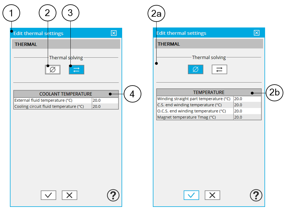
| 1 | Dialog box to define the thermal settings.Buttons allow to choose one of the three thermal solving modes |
| 2 | The first option of thermal setting is to run the test with only electromagnetic computation without any thermal analysis. This option is the default one available for all the tests. |
| 2a | Dialog box allowing to define the machine active components winding and magnets temperatures to run test without any thermal analysis. |
| 2b | Temperatures of the machine active components to be considered for characterizing the physical properties of the associated materials. |
| 3 | Thermal solving mode with iterative process between electromagnetic and thermal computations until the convergence. The selection of this mode of computation means that we must define a driving cycle as an input of the test |
| 4 | Initial temperatures of the machine active components winding and magnets. These temperatures are used to initialize the electromagnetic-thermal process of computation. |
| 5 | Definition of coolant temperatures to be considered:
|
- The external fluid temperature corresponds to the temperature of the fluid surrounding the machine. It is also considered as the temperature at the “infinite” for the computation of radiation from the frame to the infinite.
- The cooling circuit fluid temperature is relevant only when a cooling circuit has been added by the user in the design environment. In this case, this input describes its fluid inlet temperature.
For more details, please refer to the section dedicated to the “thermal settings”.
3. Power electronics parameters
Dialog box to define the power electronics parameters:
- Inverter control strategy
- Inputs for evaluating the power electronics stage losses
For more details, please refer to the section dedicated to the “Power electronics mode settings”.
4. Mechanical loss model parameters
Dialog box to define mechanical loss computation model.
For more details, please refer to the section dedicated to the “Mechanical loss model settings”.