Selection modes in GUI
Section selection mode
The process for choosing the section in which user inputs are defined is implemented in the winding area as illustrated below
 |
|
| Scrolling selection bar – Winding environment | |
| 1 | Scrolling selection bar where Winding, Coil, End-winding, X-Factor and Potting sections can be selected. |
| 2 | Section data can be reached thanks to shortcuts. |
| 3 | Arrow allows to scroll the bar to reach other sections (on the right or the left) when needed. |
| 4 | The bar slides on the right to allow reaching Potting section. |
 |
|
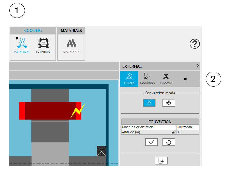
| Scrolling selection bar – External cooling area | |
| 1 | External cooling area of Motor Factory design environment. |
| 2 | Scrolling selection bar where Fluidic, Radiation, X-Factor sections can be selected. In that case, all the sections can be reached without sliding the bar. |
 |
|
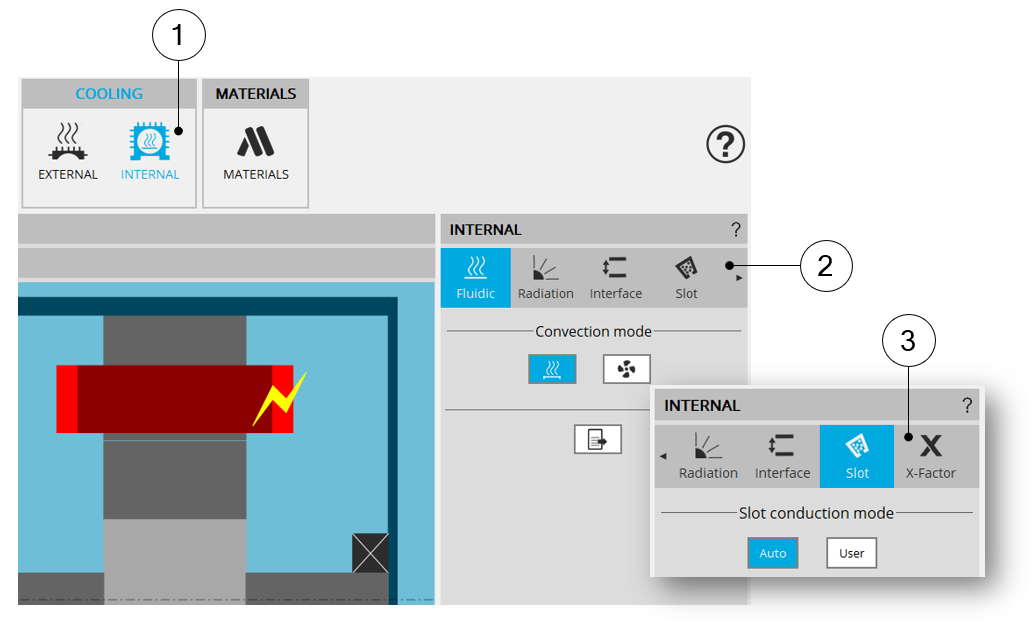
| Scrolling selection bar – Internal cooling area | |
| 1 | Internal cooling area of Motor Factory design environment. |
| 2 | Scrolling selection bar where Fluidic, Radiation, Interface, Slot sections can be selected. |
| 3 | The bar slides on the right to allow reaching X-Factor section. |
2. Multiple choices for inputs
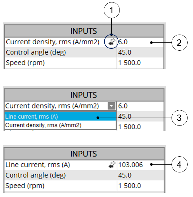
A process allowing Multiple choices for selecting the type of user’s inputs has been implemented. This allows giving users several choices within only one input line.
Please see the below example showing the different ways to define the electrical current in conductors.
 |
|
| Scrolling selection bar – External cooling area | |
| 1 | Icon allowing to give multiple choices to the users. |
| 2 | First choice = Current density (A/mm²). |
| 3 | In that case two choices are possible: either the current density or the
line current. Whatever is the choice the units and the corresponding data are updated. |
| 4 | Second choice = Line current, rms (A). |
3. Auto/User mode switch
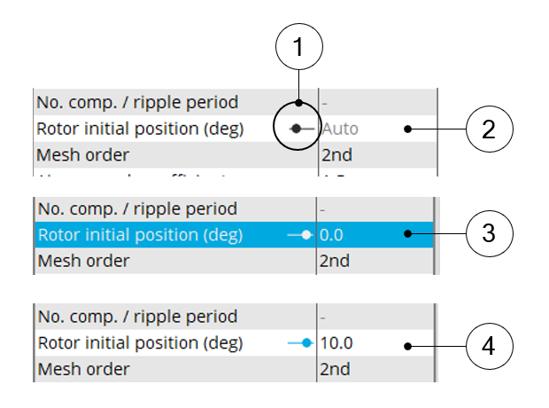
A process allowing to switch between two types of answer (Auto or user for example) has been implemented.
For example, when the “Rotor initial position mode” is set to “Auto”, the initial position of the rotor is automatically defined by an internal process.
When the “Rotor initial position” is set to “User input” (i.e. toggle button on the right), the initial position of the rotor to be considered for computation must be set by the user in the field « Rotor initial position ».
 |
|
| Auto/User mode switch – Example of application | |
| 1 | Icon allowing to switch between two types of answer. |
| 2 | First position: automatic mode |
| 3 | Second position - toggle button on the right – One can write a data in the field |
| 4 | The toggle button is blue, the data is taken into account. |