Simulate
1. Import a part in Motor Factory
The parts are built to be used in Motor Factory.
In Motor Factory, in the DESIGN area, either in MAGNET environment or in the SLOT environment it is possible to modify the topology (the shape) based upon the inner magnet or outer slot.
This corresponds to importation of a part from “Part Library”.
In Part Factory, the PART function of the test area allows testing the capability of the considered part to be imported in Motor Factory and by considering the sector defined with specific structural data.
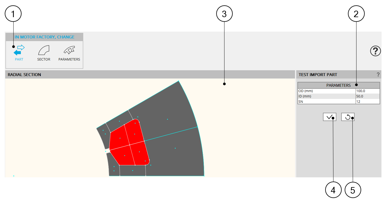
Below is the illustration of the TEST environment and import PART function.
 |
|
| Test import Part | |
| 1 | Section of the first test function: PART. It allows testing the capability to import the part in a sector whose main three dimensions are defined in zone 2. |
| 2 | User input parameters to define the three main dimensions of the reference sector (structural data). |
| 3 | The sector which represents the part is displayed on the central screen
of the design environment of Part Factory.In Part Factory intersection of
lines can be viewed. Note: A right click on the mouse
allows resetting the zoom if the part becomes invisible. |
| 4 | Validation of user input parameter values. |
| 5 | Reset of user input parameter values. The default values are defined by the properties described in the associated Excel file. |
2. Modify the structural data
Inside Motor Factory, in the DESIGN area, it is possible to modify the structural data of the machine.
The modification of the structural data has an impact on the position of the part in the reference sector.
The compatibility of the new position of the part in the sector must be checked.
In Part Factory, the SECTOR function of the test area allows to test how the considered part interact with the structural data of the reference sector in which it is defined.
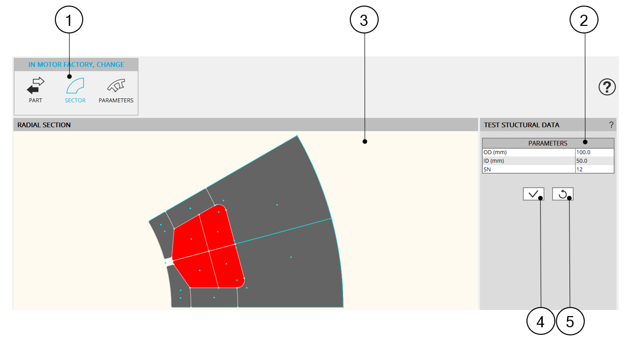
Below is the illustration of the TEST environment and the “SECTOR” modification function.
 |
|
| Modification of the sector parameters | |
| 1 | Section of the second test function: SECTOR. It allows testing how the considered part interacts with the structural data of the reference sector in which it is defined. The user input parameters are the main three dimensions of the sector defined in zone 2. |
| 2 | User input parameters define the three main dimensions of the reference sector (structural data). |
| 3 | The sector which represents the part is displayed on the central screen
of the design environment of Part Factory. In Part Factory intersection of
lines can be viewed. Note: A right click on the
mouse allows to reset the zoom if the part becomes
invisible. |
| 4 | Validation of user input parameter values. |
| 5 | Reset of user input parameter values. The default values are defined by the properties described in the associated Excel file. |
3. Modify user input parameters
The robustness of the parameterized part topology must be checked.
In Part Factory, the PARAMETERS function of the test area allows testing the robustness of the part when all its user input parameters are changed.
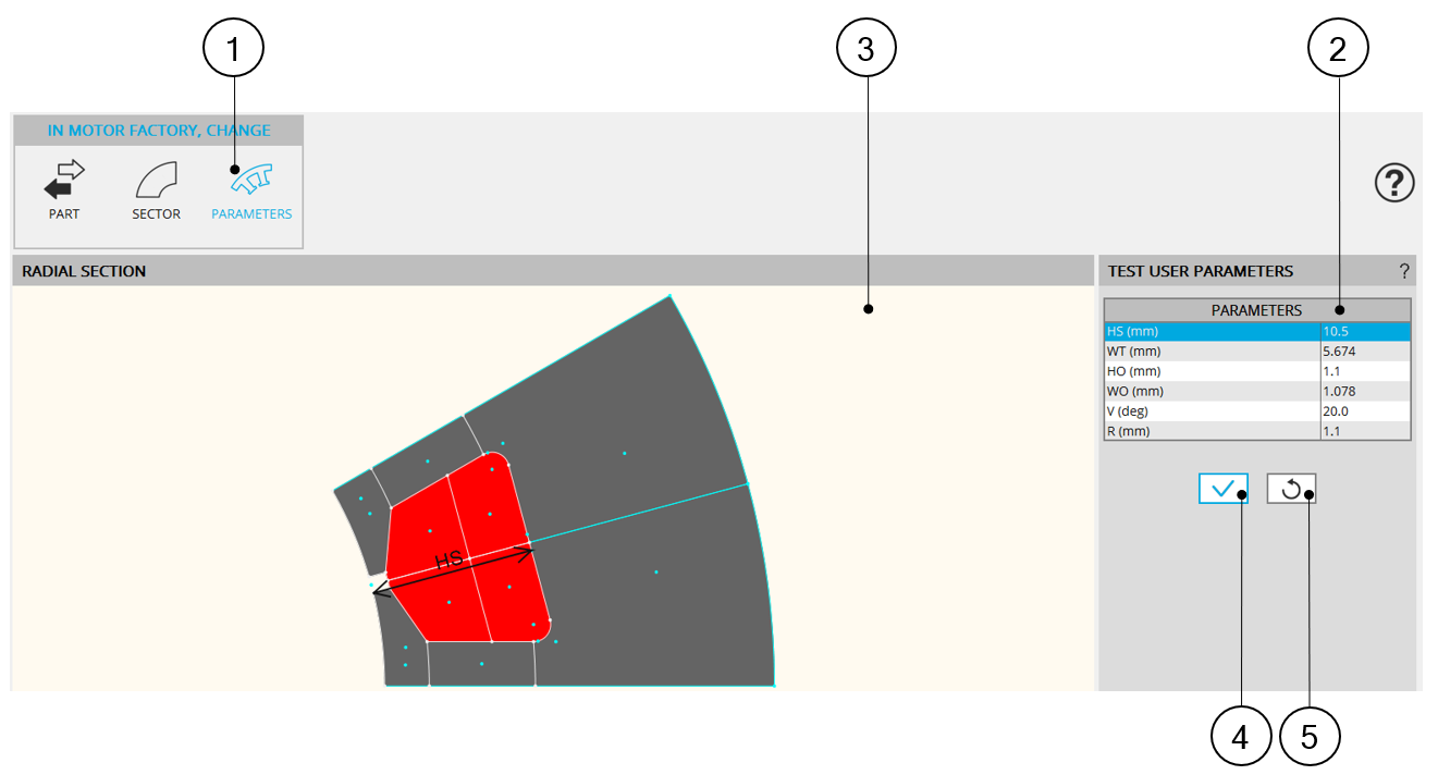
Below is the illustration of the TEST environment and the “PARAMETERS” modification function.
 |
|
| Modification of the part parameters | |
| 1 | Section of the third test function: PARAMETERS. It allows testing the robustness of the part when all its user input parameters are changed. The user input parameter corresponds to the input parameter of the considered part to test. |
| 2 | User input parameters defines the dimensions of the considered part to be tested. |
| 3 | The sector which represents the part is displayed on the central screen
of the design environment of Part Factory. In Part Factory intersection of
lines can be viewed. Note: A right click on the mouse
allows resetting the zoom if the part becomes invisible. |
| 4 | Validation of user input parameter values. |
| 5 | Reset of user input parameter values. The default values are defined by the properties described in the associated Excel file. |