LoRaWAN Overview

LoRaWAN Network Fundamentals

(Most of the information here is reproduced from the Semtech LoRa Developer Portal)
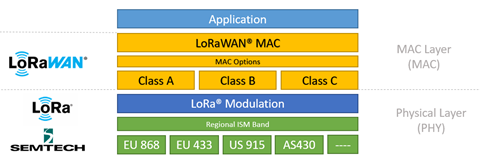
To fully understand LoRaWAN networks, we will start with a look at the technology stack. As shown in the figure below, LoRa is the physical (PHY) layer, i.e., the wireless modulation used to create the long-range communication link. LoRaWAN is an open networking protocol that delivers secure bi-directional communication, mobility, and localization services standardized and maintained by the LoRa Alliance.


Figure 1.

LoRaWAN Network Elements: An Introduction

Now that we have a basic understanding of LoRa, we will examine the architecture of a LoRaWAN network.

The figure below shows a typical LoRaWAN network implementation from end to end.


Figure 2.

Let us examine this diagram in smaller pieces.

LoRa-based End Devices
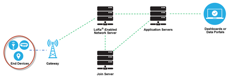
A LoRaWAN-enabled end device is a sensor or an actuator which is wirelessly connected to a LoRaWAN network through radio gateways using LoRa RF Modulation.


Figure 3.

In the majority of applications, an end device is an autonomous, often battery-operated sensor that digitizes physical conditions and environmental events. Typical use cases for an actuator include: street lighting, wireless locks, water valve shut off, leak prevention, among others.

When they are being manufactured, LoRa-based devices are assigned several unique identifiers. These identifiers are used to securely activate and administer the device, to ensure the safe transport of packets over a private or public network and to deliver encrypted data to the Cloud.

LoRaWAN Gateways
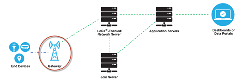
A LoRaWAN gateway receives LoRa modulated RF messages from any end device in hearing distance and forwards these data messages to the LoRaWAN network server (LNS), which is connected through an IP backbone. There is no fixed association between an end device and a specific gateway. Instead, the same sensor can be served by multiple gateways in the area. With LoRaWAN, each uplink packet sent by the end-device will be received by all gateways within reach, as illustrated in the figure above. This arrangement significantly reduces packet error rate (since the chances that at least one gateway will receive the message are very high), significantly reduces battery overhead for mobile/nomadic sensors, and allows for low-cost geolocation (assuming the gateways in question are geolocation-capable).


Figure 4.
The IP traffic from a gateway to the network server can be backhauled via Wi-Fi, hardwired Ethernet or via a Cellular connection. LoRaWAN gateways operate entirely at the physical layer and, in essence, are nothing but LoRa radio message forwarders. They only check the data integrity of each incoming LoRa RF message. If the integrity is not intact, that is, if the CRC is incorrect, the message will be dropped. If correct the gateway will forward it to the LNS, together with some metadata that includes the receive RSSI level of the message as well as an optional timestamp. For LoRaWAN downlinks, a gateway executes transmission requests coming from the LNS without any interpretation of the payload. Since multiple gateways can receive the same LoRa RF message from a single end device, the LNS performs data de-duplication and deletes all copies. Based on the RSSI levels of the identical messages, the network server typically selects the gateway that received the message with the best RSSI when transmitting a downlink message because that gateway is the one closest to the end device in question.


Figure 5.

Furthermore, LoRa allows for scalable, cost-optimized gateway implementation, depending on deployment objectives. For example, in North America, 8-, 16-, and 64-channel gateways are available.

The 8-channel gateways are the least expensive. The type of gateway needed will depend on the use case. Eight- and 16-channel gateways are available for both indoor and outdoor use. Sixty-four channel gateways are only available in a carrier-grade variant. This type of gateway is intended for deployment in such places as cell towers, the rooftops of very tall buildings, etc.

Network Server
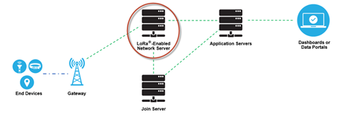
The LoRaWAN network server (LNS) manages the entire network, dynamically controls the network parameters to adapt the system to ever-changing conditions, and establishes secure 128-bit AES connections for the transport of both the end to end data (from LoRaWAN end device to the end users Application in the Cloud) as well as for the control of traffic that flows from the LoRaWAN end device to the LNS (and back). The network server ensures the authenticity of every sensor on the network and the integrity of every message. At the same time, the network server cannot see or access the application data.


Figure 6.
In general, all LoRaWAN network servers share the following features:
  • Device address checking
  • Frame authentication and frame counter management
  • Acknowledgements of received messages
  • Adapting data rates using the ADR protocol
  • Responding to all MAC layer requests coming from the device,
  • Forwarding uplink application payloads to the appropriate application servers
  • Queuing of downlink payloads coming from any Application Server to any device connected to the network
  • Forwarding Join-request and Join-accept messages between the devices and the join server

Application Servers

Application servers are responsible for securely handling, managing and interpreting sensor application data. They also generate all the application-layer downlink payloads to the connected end devices.
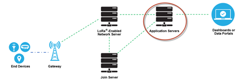


Figure 7.

Join Server

The join server manages the over-the-air activation process for end devices to be added to the network.

The join server contains the information required to process uplink join-request frames and generate the downlink join-accept frames. It signals to the network server which application server should be connected to the end-device, and performs the network and application session encryption key derivations. It communicates the Network Session Key of the device to the network server, and the Application Session Key to the corresponding application server.


For that purpose, the join server must contain the following information for each end-device under its control:
  • DevEUI (end-device serial unique identifier)
  • AppKey (application encryption key)
  • NwkKey (network encryption key)
  • Application Server identifier
  • End-Device Service Profile
Figure 8.

LoRaWAN Network Elements: Device Commissioning

For the sake of security, quality of service, billing, and other needs, devices must be commissioned and activated on the network at the start of operation. The commissioning process securely aligns each device and the network with respect to essential provisioning parameters (such as identifiers, encryption keys, and server locations).

The LoRaWAN specification allows for two types of activation: Over-the-Air Activation (OTAA) (preferred) and Activation by Personalization (ABP).

LoRaWAN Network Elements: Security

There are two key elements to the security of a LoRaWAN network: the join procedure and message authentication. The join procedure establishes mutual authentication between an end device and the LoRaWAN network to which it is connected. Only authorized devices are allowed to join the network. LoRaWAN MAC and application messages are origin-authenticated, integrity-protected and encrypted end-to-end (i.e., from end device to the application server and vice versa).

These security features ensure that:
  • Network traffic has not been altered
  • Only legitimate devices are connected to the LoRaWAN network
  • Network traffic cannot be listened to (no eavesdropping)
  • Network traffic cannot be captured and replayed