Urban Propagation
The workflow for a typical urban propagation simulation is to use WallMan to create the geometry, Feko or AMan to produce the antenna pattern and ProMan to simulate the model and view the results.
- Use WallMan to produce the geometry database.
This can be done by creating it from scratch (possibly by drawing it with the aid of an existing bitmap) but is usually done by importing and converting it from a third-party source, making modifications if needed, and saving it in WinProp format.
Optionally, an urban database can be pre-processed in WallMan to establish visibility relations for ray-tracing, to avoid repetitive work during the actual ray-tracing later in ProMan. In an urban database, the objects are polygonal cylinders with individual heights. Vegetation can be included as well. For more detail in the buildings, use indoor (even if the scenario is really outdoor) or hybrid urban / indoor.Figure 1. Example urban database in WallMan. Buildings are polygonal objects. 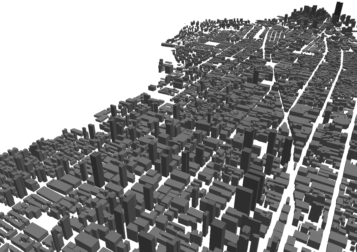
- Use Feko or AMan to
produce the antenna pattern.For actual antenna design and simulation, Feko (part of the Altair HyperWorks Products) can be used. Feko can export antenna patterns in the correct format to be used by ProMan.
AMan is not an antenna simulator. Instead, it is a tool that enables you to produce an antenna pattern in WinProp format. The pattern may be converted from another source. AMan can generate an approximate 3D antenna pattern in cases where only two 2D pattern cuts are available and can combine antenna patterns to produce that of a base station.
Figure 2. Base station patterns produced in AMan by combining individual antenna patterns with the geometrical and material specifications of the base station mounting structure. 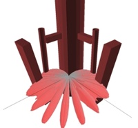
- Start a new urban propagation project in ProMan based
on the database produced by WallMan. Elevation data can be included at the time of importing the urban database. The key menu in ProMan is . This brings up a window with multiple tabs, specific to the simulation of interest, where many simulation parameters are specified.In this menu, you also select the simulation method. Several empirical models are fast but may be less accurate than rigorous methods. Of the more-rigorous methods, the dominant path model is recommended for pure coverage studies without multipath effects, while standard ray-tracing or intelligent ray-tracing is recommended in case the temporal or angular properties of the radio channel are of interest.
Figure 3. The key menu in ProMan is . 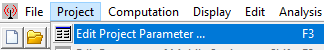
- Run the simulation in ProMan through the
Computation menu or by clicking the RUN
PRO button.
Figure 4. Click the RUN PRO button to run the simulation. 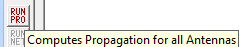
- Inspect the results in the same ProMan interface.
Expand the tree on the left if necessary to access the results.
Figure 5. Example of urban propagation results. 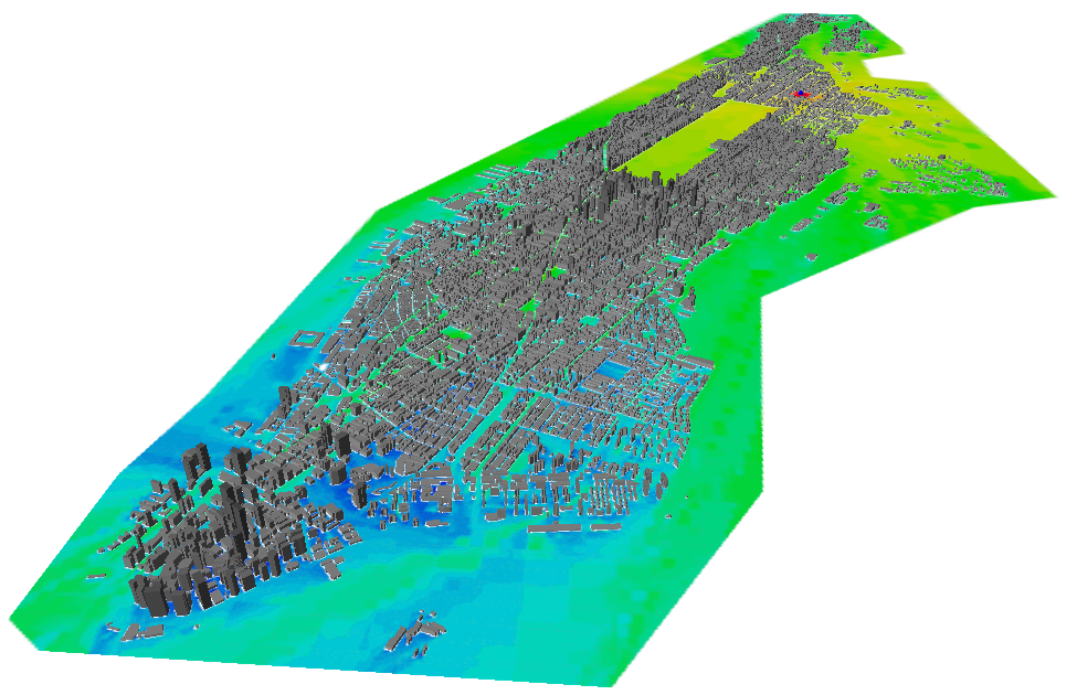
Fields can optionally penetrate into the buildings, but interior details of the buildings are not included. While fields can travel into an urban building, they cannot travel through an urban building and come out on the other side.