Generation of Antenna-Array Radiation Patterns
Define the array elements with optional amplitude tapering, and generate the radiation pattern to use in any ProMan project, for example, for a 5G base station or for a radar.
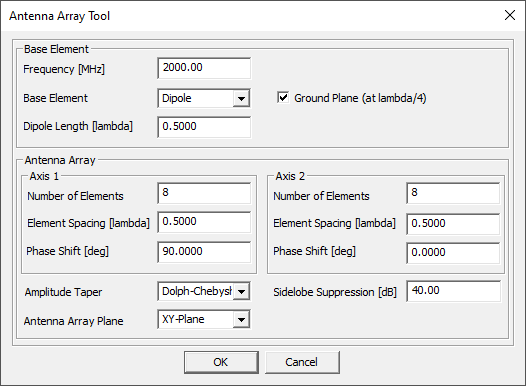
Array Tool Options
The antenna array is rectangular.
- Base Element
-
- Isotropic and Dipole
- These options enable you to add a reflecting plate at a quarter-wavelength distance, as is commonly used, to produce a beam in one direction and avoid a backlobe of equal strength.
- External
- This option enables you to select a unit-cell antenna patterns from Feko in .ffe format.
- Amplitude Taper
- Uniform, Triangular, Cosine-shaped, Dolph-Chebyshev
Triangular and Cosine-shaped tapering will reduce the side-lobe level relative to Uniform excitation. These three cases have in common that side lobes far from the main beam will be lower than those close to the main lobe. With Dolph-Chebyshev tapering you can choose the side-lobe level, upon which all side lobes will obtain that level.
- Antenna Array Plane
- XY Plane (the array is horizontal and radiates in vertical directions)
or XZ Plane (the array is vertical and radiates mainly in horizontal
directions).
When you assign this pattern later in ProMan to a transmitter or receiver, in the Cell dialog under the Sites definition, you can adjust its azimuth and elevation.
For a scan angle of 30° off boresight in one of the principal planes, the phase shift along the corresponding axis has to be 90°.
Array Tool Calculation
The calculation is based on the product of a single-element antenna pattern and an array factor.
- the neighbor-cell coupling is not included in the single-element dipole pattern
- if the dipole length equals the element spacing, the dipole won’t physically touch a neighbor
As for the external base element, if you use a unit-cell antenna element pattern from a Feko project with periodic boundary conditions, then neighbor-cell coupling will be included.
The array factor is based on number of elements, element spacing, phase shift, and amplitude taper. No distinction is made between antenna elements near the center and near an edge of the array. This is customary in this type of calculation where the full-wave analysis of the complete array is avoided.
When clicking OK, you are prompted for a name and a location for the resulting .ffe file. The file is written to disk; the pattern is not automatically displayed. Use in the main AMan menu to load the file and inspect the pattern.