Multiple Antenna Scenario Configuration (MASC)
Antenna patterns from the manufacturer of the antenna are always measured in anechoic chambers. So the mounting of the antenna at a mast or in front of a wall is not considered in the pattern. But obviously, mast and wall have a significant influence on the actual antenna pattern. MASC allows considering mast / wall, arms, tubes, radomes and their influence on the actual radiation pattern of the antenna.
Sometimes the same signal is radiated with multiple antennas (using power splitters and phase shifters) to obtain special antenna patterns (for example, quasi-omni configurations). MASC can also compute these antenna patterns based on the superposition of multiple single antennas fed with different powers and phases.
The actual antenna patterns (either 2x2D or real 3D) computed with MASC are saved in the standard file formats of AMan and can be exported to many other file formats (for example, .msi, .pln). So, the computed patterns can also be used together with other prediction models and radio network planning tools.
The scenario including mast, arms, tubes, radomes is modeled in 3D and automatically generated based on some parameters (distances, lengths, materials) defined by the user. MASC generates not only all objects of the scenario automatically, but it also generates the coordinate system. So, you can focus on what is important (the properties of the individual antennas mounted at the mast), and MASC organizes the other things.
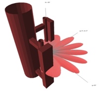
In the 2x2D mode, the vertical, as well as the horizontal pattern, contain the direction with the highest gain (at this point vertical and horizontal pattern intersect). Especially if antennas with tilts are used, this is complex because the horizontal pattern is shifted horizontally.
- Vector from the point with the highest gain towards the center of the spheroid of the computation
- Vector of Z-axis
- Center of the spheroid of computation
- Horizontal vector (no z component)
- Normal vector of the vertical antenna pattern
- Point with the highest gain
The computation can be scaled to obtain very fast first results and to get the highest achievable accuracy (requiring longer computation time).