Adding an Angled Prediction Plane
Define an additional and arbitrary polygonal prediction plane.

-
Create a polygon using one of the following workflows:
- On the Objects menu, click .
- On the Objects toolbar, click
the
 Add Polygonal Objects icon.
 - Press F7 to use the keyboard shortcut.
-
Create the general shape of the prediction plane (in this example, a
rectangle).
Figure 2. View of the model in the X/Y plane (top view). The general shape of the prediction plane is illustrated in green. 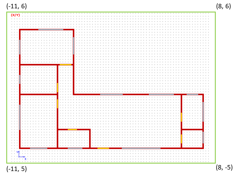
- Click twice to specify the first corner of the polygon.
- Click twice to specify corner 3 and corner 4.
- Right-click at the first corner to close the polygon.
-
Edit the coordinates of the prediction plane.
-
Click Change Type.
The Wall Type dialog is displayed.
-
Under Selected Type, from the drop-down list, select Prediction
Plane.
Figure 3. The Wall Type dialog. 
- Click OK to close the Wall Type dialog.
-
Click OK to close the Object
Properties dialog.
Figure 4. A 3D model of the building showing the angled prediction plane (indicated with a blue outline). 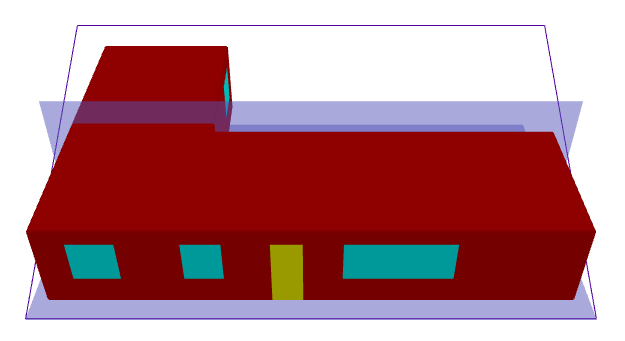
Note: The new prediction plane must also be included in the simulation when setting up the project parameters in ProMan, see Step 5.