Loft
Create a 3D surface by fitting it through two or more profile curves. You can constrain the shape using rails.
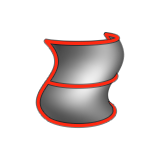
Create a Loft
Create a 3D surface by fitting it through two or more profile curves. You can constrain the shape using rails.
-
Click the Loft icon.
Edit a Loft
Modify the orientation, position, and shape of the loft.
Modify the Constraint
If surface edges were used for profiles or rails, modify the constraint to fine-tune the shape of the loft surface.
If the selection includes rails, the constraint may not be fulfilled as the shape of the rails must be compatible with the constraints.
Auto-align the Profiles
Use profiles for the loft that do not intersect the rails.
Profiles are only used as reference. This option comes with extra parameters that allow more control over the position and orientation of each profile.
- Double-click the loft to enter edit mode.
- In the guide bar, select Auto-alignment.
- Click a profile.
-
Edit the profile:
- If only 1 rail was used:
To Do this Note Reposition a profile along the rail Type a value for Point on rail 1, and then press Enter. By default, the profiles are distributed evenly along the rail. Realign the profiles with the rail Type a value for Point on profile, and then press Enter. By default, each profile start point is aligned with the rail. Rotate the profile around the rail's tangent Type a value for Rot. tangent, and then press Enter. Rotate the profile around the rail's normal Type a value for Rot. normal, and then press Enter. Rotate the profile around an axis that is perpendicular to the rail's tangent and normal Type a value for Rot. vertical, and then press Enter. Reverse the order of the profiles along the rail Click Reverse profiles order. - If more than 1 rail was used:
To Do this Reposition a profile on a point along the first rail Type a value for Point on rail 1, and then press Enter. Reposition a profile on a point along the second rail Type a value for Point on rail 2, and then press Enter. Lock values for point on rail This option is enabled by default to move the profile along both rails. To disable click Lock values. Point 1 on profile To reposition a profile on a point of the profile, type a value for Point 1 on profile, and then press Enter. Point 2 on profile To reposition a profile on a point of the profile, type a value for Point 2 on profile, and then press Enter. Swap values for point on profile To swap the values for Point 1 on profile and Point 2 on profile, click Swap values. Profile rotation To rotate the profile around the center line of the two rails, type a value for Profile rotation, and then press Enter. Direction of rail 2 To invert the direction of the second rail, click Invert rail 2. Profile order To reverse profile order along the rail, click Reverse profiles order.
- If only 1 rail was used:
- Right-click and mouse through the check mark to exit, or double-right-click.