Analyst
In this section, you will be taking the place of an Analyst who must use Pulse solve an engineering problem.
You received a request from the design team to evaluate the geometry of a hull. They want to know whether or not the displacement on the central part of the body is greater than 3 mm when a uniform pressure force is applied to it.
Here are the provided inputs:
- The HM File: Hull.hm
- The Pulse Project: Analyst_Tutorial.ppls
- Batch Meshing Input Files
- Pressure Force Values: 1.2, 1.5, 1.8
-
Click .
- Browse to and open the location of the Hull_Structural_Analysis.ppls in the folder.
 Figure 1.
 -
From the Project tab, click on the
Analyst_Tutorial project.
-
Enter the properties as seen below.
 Figure 2.
-
Enter the properties as seen below.
-
Press Run to execute the
process.
 Figure 3. The Batch Mesher dialog opens.
 -
In the Batch Mesher dialog, select the requisite inputs
from theThree Profiles
Tutorial>Analyst>BatchMesher
folder.
-
For Criteria File, select
Hull_45mm.criteria.
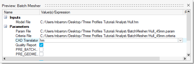 Figure 4.
-
For Criteria File, select
Hull_45mm.criteria.
-
Check Quality Report and
POST_BATCH so that a mesh quality report is
generated. This also allows you to select the script to perform after the
Batch Mesher dialog closes.
 Figure 5.
 -
From the Three Profiles
Tutorial>Analyst>BatchMesher
folder, select the POST_BATCH parameters:
- For Post Batch Script, select OptistructOutput.tcl.
- For Post Batch Proc, select optistructexport.
 Figure 6.
 -
Complete the Model_SetUp module inputs. Note that the
Material Input parameters begin completed by default.
-
Enter 12 for the Thickness variable.
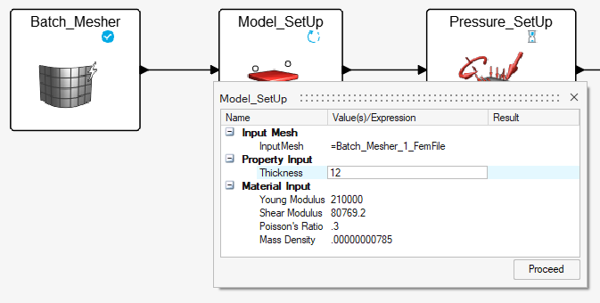 Figure 7.
-
Enter 12 for the Thickness variable.
-
Complete the Pressure_SetUp module.
-
Enter 1 for the Pressure variable.
 Figure 8.
-
Enter 1 for the Pressure variable.
-
Create the model's boundary conditions.
-
Click on the green arrow to create SPCs on the selected nodes.
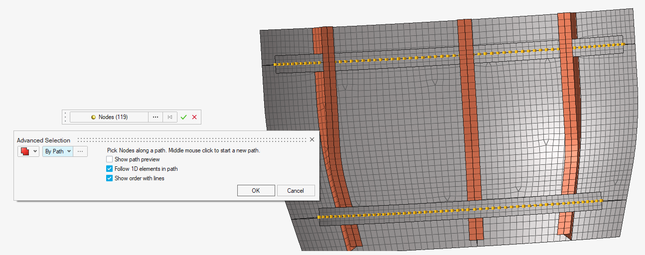 Figure 9.
-
Click on the green arrow to create SPCs on the selected nodes.
-
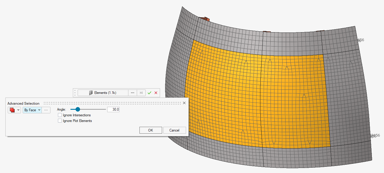
Select the following elements by face.
-
Click the green arrow to create the pressure load.
-
Close HyperWorks.
OptiStruct has the required inputs to proceed.
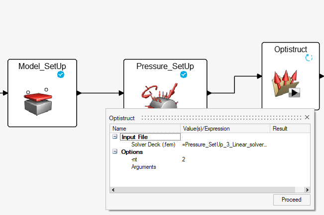 Figure 10.
-
Click the green arrow to create the pressure load.
-
Click Proceed and then immediately click the
Pause button at the top of the screen.
 Figure 11. The process pauses and is maintained in the current run folder.
 -
Right click on the Optistruct task and then click
Unrealize.
 Figure 12. The circle on the module will appear blank. Task will appear as not executed.
 -
Right click the module and click Restart Run from Here.
If desired, the number of cpus (-nt) can be changed in Edit
Input.
 Figure 13. The process will restart and the Hyperworks-HV module will run. The h3d results will be created and displaced in HyperView.
 -
Add the displacement contour.
- Check that the maximum displacement is not greater than 3 mm.
 Figure 14.
 -
Click Stop.
 Figure 15.
 -
From the Project tab, click
Study1.
-
Right click on Pressure_1 and click
Duplicate Study.
 Figure 16. The study is duplicated so other evaluations can be performed.
 -
Rename the new studies to Pressure_1.5 and
Pressure_1.8.
 Figure 17.
-
Right click on Pressure_1 and click
Duplicate Study.
-
Save the file with
- Name the file as desired and save.
 Figure 18.
 -
Navigate to the location in which the project was saved. The .ppls file and the
three study folders will be present.
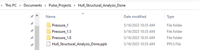 Figure 19.
 -
Open the Pressure_1 folder. The scripts folder contains
the necessary resources to execute the process, and the .ppls file contains the
process information.
 Figure 20.
 - Open the run_001 folder for an example of the files generated by executing the study. Each time a study is executed, the results will appear in a similar folder.
 Figure 21.