PollEx DFA is an assembly status checking tool set for PCB
design based on 3D package library. PollEx DFA is a
software option of PollEx PCB. Based on PollEx PCB design and imported matching 3D package shape,
PollEx DFA provides full board 3D model and assembly
checking, which is impossible with 2D data. For the detected violations, PollEx DFA sorts them according to their types. This helps
manufacturing engineers to reduce cost and time.
Launch PollEx PCB.
Open the PollEx PCB layout design file.
From the menu bar, click File > Open and open the
PollEx_PCB_Sample_r<revision
number>.pdbb file from
C:\ProgramData\altair\PollEx\<version>\Examples\PollEx_PCB_Sample_r<revision_number>.pdbb.
Refer to the PCB manual
for how to use the PollEx PCB viewer.
Save as Project.
PollEx PCB operates on a design project database
which contains entire data of a PCB design including the materials, parts,
physical layout, analysis models and analysis result data. With the use of a
unified design project database, this application can be commonly used by
multiple engineering disciplines.
From the menu bar, click File > Save As Project to create a new PollEx project directory.
The sample PCB design name displays as the New project
name.
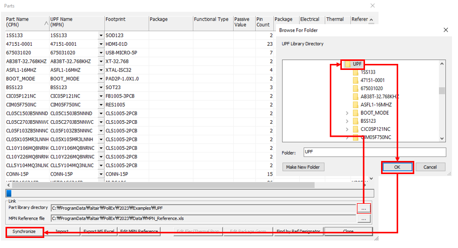
Link Unified Part Libraries.
From the menu bar, click Properties > Parts.
Click in the Part Library Directory.
Select the UPF folder in the path
(C:\ProgramData\altair\PollEx\<version>\Examples\UPF)
and click Synchronize.
Figure 1. You can check the linked data in the package, electrical and
thermal columns for 3D package shape for SI and Thermal analysis.
Click Close.
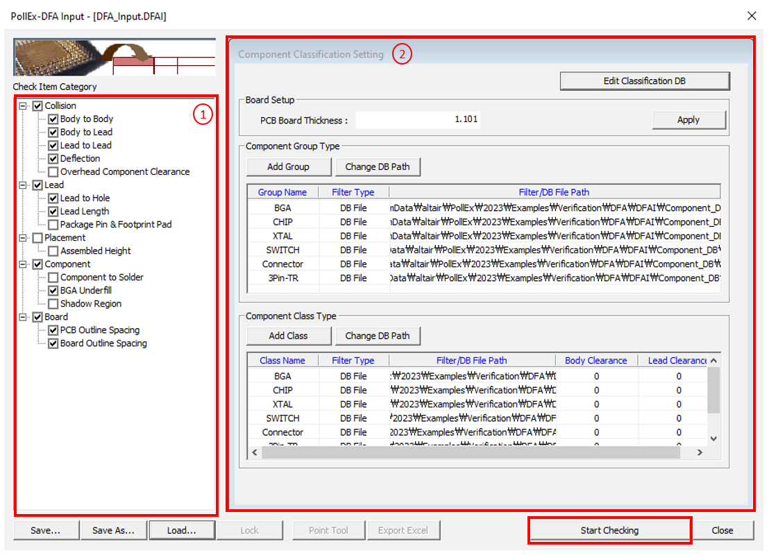
Open DFA Input setting file.
From the menu bar, click Verification > DFA > Input.
To load the DFA rule file, click Load and select the
DFA_Input.DFAI file from
C:\ProgramData\altair\PollEx\<version>\Examples\Verification\DFA\DFAI
.
Click Open.
Check DFA Input file and verification.
Figure 2.
In the Check Item Category menu, you can see the lists of checking items. In
the Component Classification Setting, you can classify a component
group.
Refer to the DFA manual
for the detailed rule settings.
Click Start Checking to run the
verification.
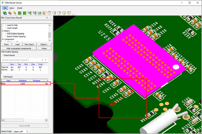
View and save DFA verification result.
The test results display on the screen (Pass or Fail).
Click Save to save the verification result file
with the extension *.DFAR.
Check the DFA verification results by clicking PCB Outline
Spacing from the item list.
You can check detailed information of the No Good (fail) items from
the lists.Figure 3. The above image is an example where the U205 part fails due to not
complying with 7mm clearance from the PCB board outline.
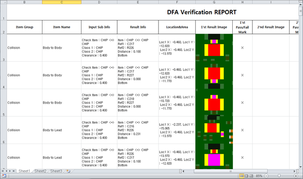
Excel export of DFA verification result.
From the menu bar, click Export > User Defined Excel Format to execute the wizard.
Click Load and select the
PollEx_DFA.DFAE file from
C:\ProgramData\altair\PollEx\<version>\Examples\Verification\DFA\DFAE.