IR-Drop
IR drop refers to a voltage drop that appears at the resistance component of power network.
IR drop is the electrical potential difference between power source and load component during a current flow. If the voltage level supplied to the component is lowered due to IR-Drop, the system malfunctions or the Rising/Falling time of the signal is delayed, causing a Signal Integrity problem.
Therefore, in order for the component to work properly, it is necessary to check whether the amount of IR-Drop is within the limit value allowed by the component.
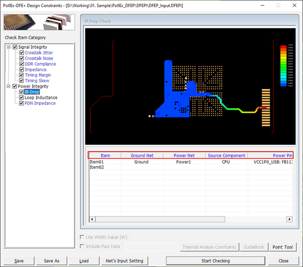
This item checks whether the voltage level of the specified component is lower than the specified level.

Figure 1.
- Item: Sub item name. You can enter arbitrary name.
- Ground Net: Select target ground net groups to be tested. Allow multiple net groups.
- Power Net: Select target power net groups to be tested. Allow multiple net groups.
- Source Component: Select component groups that supply power.
- Power Pin: Upon clicking this field, the Selected Power Net Pins dialog will be
open. You can set the required power source pins and load pins for each power
net.
- Use auto setting: When this option is selected, among all the pins connected to each power net, the pins connected to the source component are automatically selected as source pins, and the remaining pins are automatically selected as load pins. The setting contents cannot be changed.
- Use user defined setting: Selecting this option allows the user to arbitrarily select power source pins and power load pins. And users can input the voltage of each net and modify the Current Sink of the Load Pins.
- Allowed IR-Drop: Upon clicking this field, the IR-Drop dialog will be open. You
can set maximum allowable IR-Drop value.
- Use pre-defined IR-Drop: Upon selecting this option, DFE will use the IR-Drop value preset in the component.
- Use user defined IR-Drop: Upon selecting this option, you can arbitrarily set allowable IR-Drop value or ratio(%).