Type 1: Package Type
Generate a package type logic symbol using the Logic Generation Wizard.
-
Define name, spacing, and dimensions.
-
Pin Name Location: Define the location of the pin name.
The following parameters can be defined:
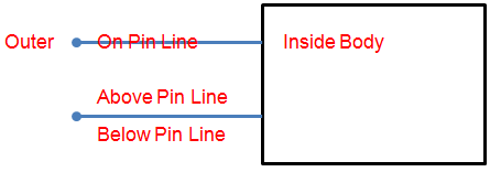
Figure 1. -
Reference Designator Location: Define the location of the reference
designator text.
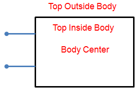
Figure 2. -
Pin Length: Define the pin length.
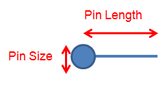
Figure 3. -
Part Name/Value Location: Define the location of the part name and
value.
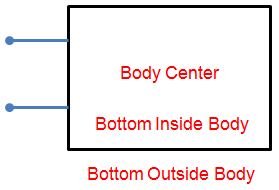
Figure 4.
-
Pin Name Location: Define the location of the pin name.
-
Confirm the created logic symbol.
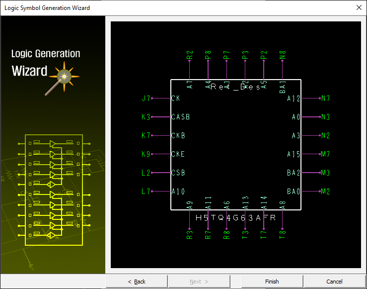
Figure 5.