Analysis Part Setup Dialog Parameters
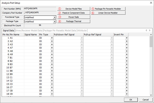
Figure 1.
- Device Model File: Specify/register the IC models in the form of IBIS,
SPICE, Linear Device, S-Parameter, Package Parasitic, and Y/Z
parameters.
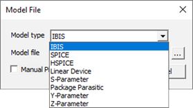
Figure 2.To register and use the model in Linear Device form, this model should be prepared using the Linear Device Modeler menu.
The model in the form of Package Parasitic should be prepared using the Package Pin Parasitic Modeler menu.
- Passive Component Data: Specify the passive part values in the form of RLC,
SPICE, and S-Parameter.
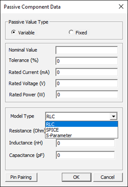
Figure 3.- Passive Value Type:
- Variable: User can setup nominal value of passive component excepting Model type of SPICE and S-Parameter.
- Fixed: User can modify properties of passive component value and specify the passive part values in the form of RLC, SPICE model and S-Parameter model. User can also select and use the bundle type of SPICE model.
- In Power Integrity analysis, all passive component data is applied to only fixed type.
- Passive Value Type:
- Power Rails: Specify the property of power rail for Power Integrity
Simulation. Before assigning the power rail, simulation model should be
assigned using Device Model Files menu. Then PollEx can extract power rail
information from simulation model. Double click the required power rail,
then Edit dialog will be displayed. You can assign DC Current, Allowable DC
Voltage Drop(V) and Target impedance.
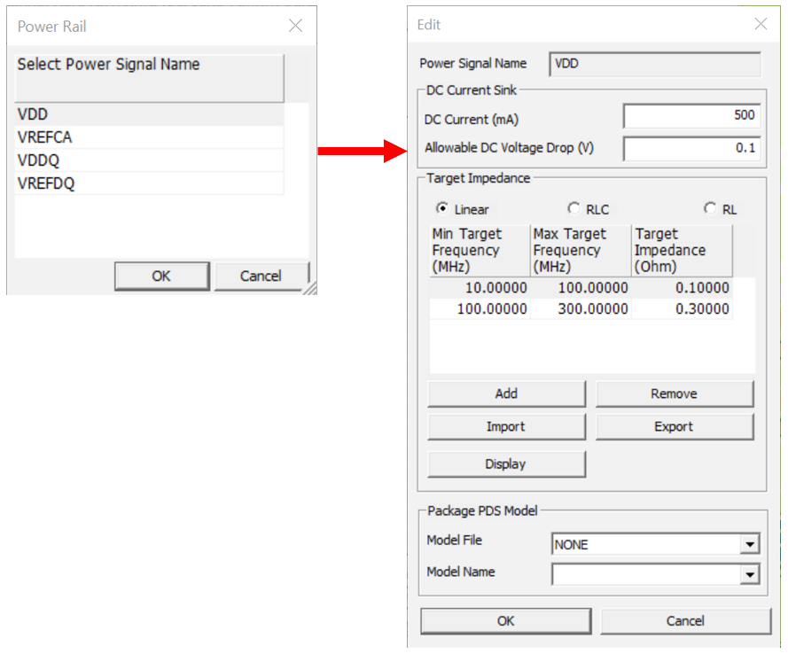
In Target Impedance, there are three types way to set up the target impedance: Linear, RLC and RL.
- Linear: Setup target frequency (Min and Max) and target
impedance value(ohm) directly.
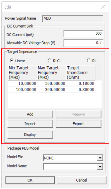 Figure 5.
 - RLC: Set up the target impedance by entering Capacitance(pF),
Resistance(ohm) and Inductance(nH) value. Click
Display to preview the corresponding
target impedance graph.
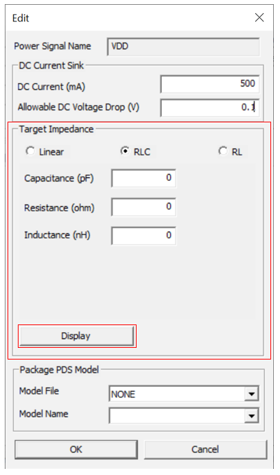 Figure 6.
 - RL: Set up the target impedance by entering Resistance(ohm) and
Inductance(nH) value. Click Display to
preview the corresponding target impedance graph.
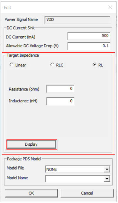 Figure 7.
- Linear: Setup target frequency (Min and Max) and target
impedance value(ohm) directly.
- Package Thermal: Specify the package thermal property and Package Geometry for Thermal Analysis.
- Package Pin Parasitic Modeler: Enable to define package pin’s RLC parasitic model having versatile sections and branches.
- Linear Device Modeler: Enable to define simple linear device model for IC pin which will be worked as one of the types among Input, Output, IO, or Terminator. Depending on the selected working type of these, user should define the bias and RLC values configuring the circuit topology.