Tutorial: Connecting Parts with Spot Welds
Tutorial Level: Beginner Create and use spot welds to connect multiple surface parts.
- Use spot welds to connect multiple surface parts
- Create spot welds at predefined points and other locations.
- Define the weld diameter
- Change the search distance
- Run an analysis
Spot welding is a common method of joining surface parts. Spot welds can be created either at predefined points, or simply by clicking on a location. When creating a spot weld, you need to define the weld diameter and which parts are being connected. Surface parts that lie within the search distance are automatically included in the spot weld, and individual parts can also be added or removed manually.
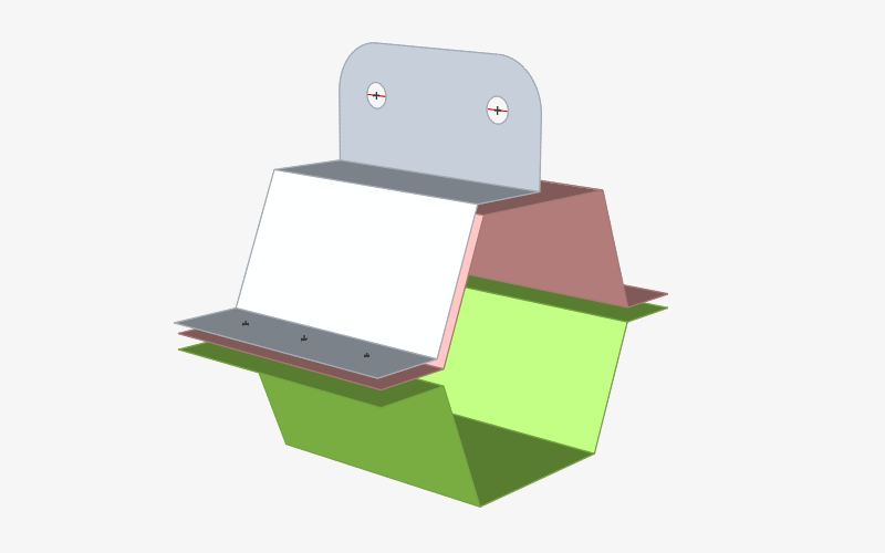
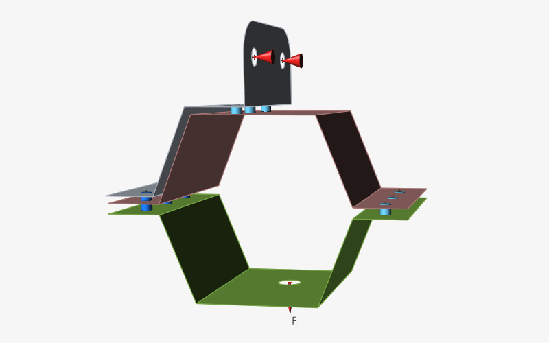
This tutorial uses a simple assembly with three surface parts and three points. The desired spot weld locations are often defined using a CAD system and then imported into Inspire, but they can also be defined in Inspire itself. The model includes predefined loads and is nearly ready to run. All that is required is to connect two parts with spot welds at one location and to connect three parts with spot welds at a second location before running the analysis.
Open the Model and Select the Unit System
-
Double-click the spotweld.stmod file to load it in the
modeling window.
- Make sure the display units in the Unit System Selector are set to MPA (mm t N s).
Create Spot Welds at Predefined Points
Create spot welds at the predefined points imported with the model.
-
Select the Spot Welds tool on the
Structure ribbon.
 Tip: To find and open a tool, press Ctrl+F. For more information, see Find and Search for Tools.
 -
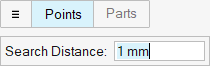
Click the
 icon on the guide bar and change the
Search Distance to 1 mm.
icon on the guide bar and change the
Search Distance to 1 mm.
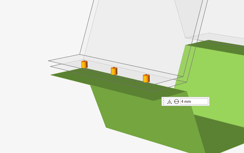
-
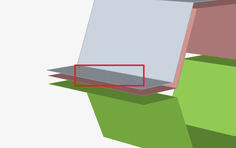
Box select the three points on the model. Note that no spot welds are created.
This is because the neighboring parts are not within the 1 mm search
distance.
-
Change the Search Distance to 5
mm and box select the points. This time, spot welds are created
between two of the surface parts.
- Press Ctrl+Z to undo.
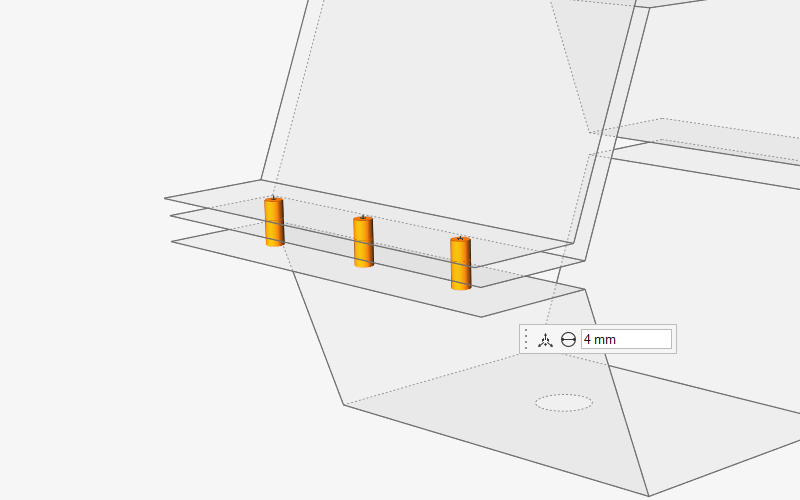
-
Change the Search Distance to 15
mm and box select the points. This time, spot welds are created
between all three of the surface parts.
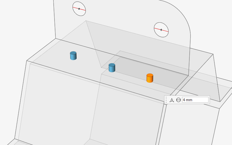
Create Spot Welds on a Surface Part
Create spot welds by clicking any location on a surface part. The weld is projected normal to the surface, and adjacent parts within the search tolerance are included in the weld.
- Change the Search Distance to 5 mm.
-
Left-click at the three locations shown below to create spot welds:
-
Press F2 to open the Model
Browser. Note that all of the spot welds have been placed into a
spot weld group.
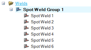
- You can select welds in the group individually, or several at once by holding the Ctrl key.
-
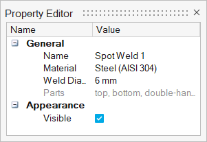
Change the Weld Diameter to 6 mm.
This updates the diameter for all of the selected welds.
- Right-click and mouse through the check mark to exit, or double-right-click.
Create Sketch Points at Weld Locations
Create sketch points to gain more precise control over where spot welds are placed.
-
Select the Points tool from the
Points/Lines icon on the
Geometry ribbon.
 Tip: To find and open a tool, press Ctrl+F. For more information, see Find and Search for Tools.
 -
Select the face on the bottom part (that is parallel to the Top part) as the
sketch plane.
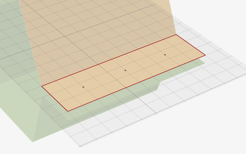
-
Click to place three sketch points as shown.
-
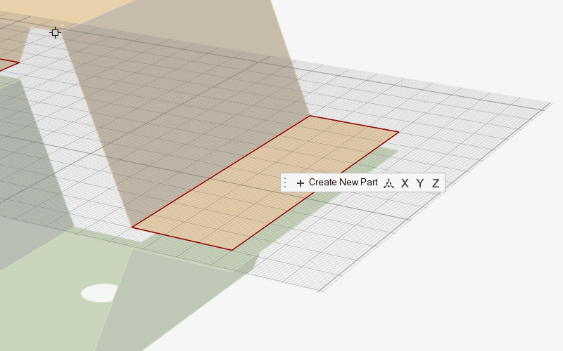
Select the Transfer Sketch from the sketching toolbar to
transfer the three points to a new part. This keeps the weld locations
independent of the geometry.

- Double-right-click to exit sketch editing mode.
- Rename the part as Weld Location Points 2 in the Model Browser.
Create Spot Welds at the New Locations
In the Model Browser, select a part that contains only points to quickly create spot welds at those points.
-
Select the Spot Welds tool on the
Structure ribbon.
Tip: To find and open a tool, press Ctrl+F. For more information, see Find and Search for Tools.
-
Click the icon on the guide bar and change the
Search Distance to 10
mm.
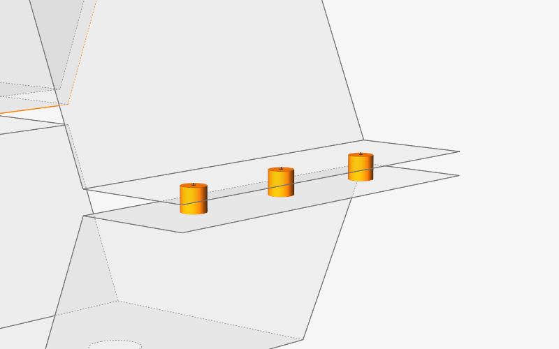
-
Select the Weld Locations Points 2 part in the Model
Browser. The spot welds are automatically created.
- Right-click and mouse through the check mark to exit, or double-right-click.
-
Press A twice to hide and then show everything in the
model.
Run an Analysis
-
Click Run Analysis
 on the Analyze icon on the
Structure ribbon.
on the Analyze icon on the
Structure ribbon.
 Tip: To find and open a tool, press Ctrl+F. For more information, see Find and Search for Tools.
 -
Run the analysis again using the settings shown below. Set the Element Size to
5.0 mm, and change the Speed to
Faster.
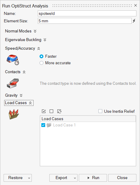
- Click Run.
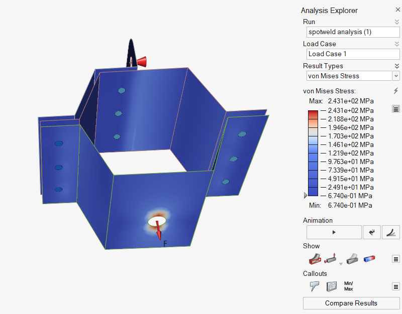
- When the run is complete, select the run in the Run Status window and click View Now to view the results.
- In the Analysis Explorer, select von Mises Stress for the Result Type.
-
Set the maximum value in the legend to 90 MPa. Note the stress concentrations
around the spot welds as expected.