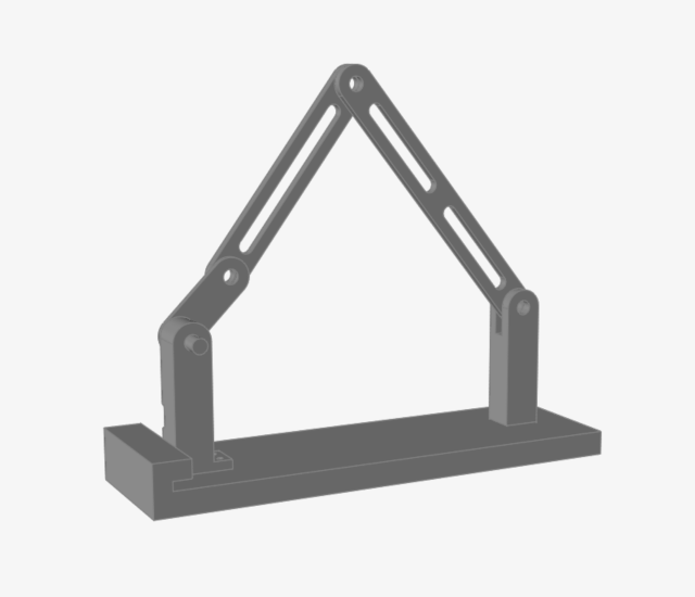
The part turns red, and the part icon in the Model Browser changes to indicate that it is a ground part.
Right-click and mouse through the check mark to exit, or double-right-click.
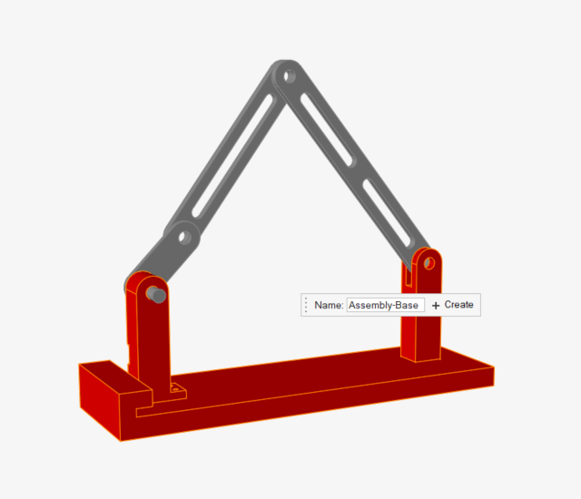
Create a Rigid Group
Select the Rigid Groups tool.
Select the Base, Mount Crank, and
Mount Clevis parts in the bottom half of the
mechanism.
The parts turn red as you select them.
Click the floating Create New Group icon to place the
parts you selected into a new rigid group.
Right-click and mouse through the check mark to exit, or double-right-click.
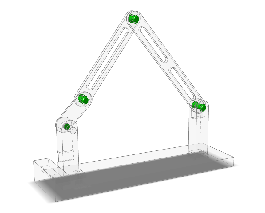
Run a Simple Motion Analysis
Click the Quick Run button on the Analyze Motion tool to
see the model in motion.
Notice that the ground parts remain stationary and some of the unconnected
parts fall due to gravity.
Note: The Quick Run is a toggle button, so you can also use it to stop an
analysis that is still running.
After the analysis has stopped running, the icon appears and you are automatically placed into
review mode. Click the Review Motion Results icon or
double-right-click to exit review mode.
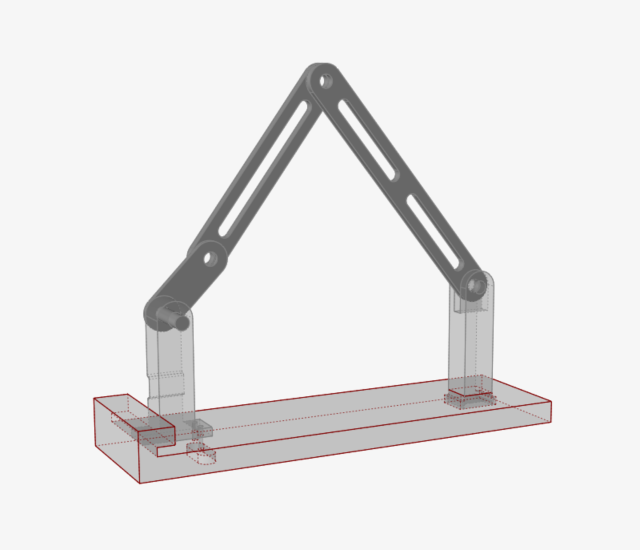
Connect Parts with Joints
Select the Joints tool.
Check that the guide bar is set to the default settings (All Parts, All,
Auto).
Click
, then the
button.
Joints are created at neighboring parts in the model. The colors
indicate the joint state (in
this case all have been set to Active).
Right-click and mouse through the check mark to exit, or double-right-click.
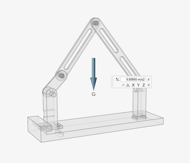
Inspect the Gravity Direction
Open the Gravity tool:
On the Motion ribbon, under Forces, select the
Gravity tool.
By default, the gravitational acceleration (G) is set to 9.80665
m/s2 in the -z
direction.
Notice that a vector is displayed which indicates the direction of
gravity.
Figure 1.
Right-click and mouse through the check mark to exit, or double-right-click.
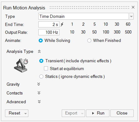
Change the Run Settings and Rerun the Analysis
Hover over the Analyze Motion tool, then click the
Run Settings icon to open the Run Motion Analysis
window.
Change the Output Rate to 100 by
entering the value in the field or clicking the 100
button.
Figure 2.
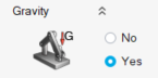
Expand the Gravity section and verify that the
Yes radio button is selected.
This is the default setting for a motion analysis.
Close the Run Motion Analysis window.
Click the Quick Run button on the Analyze Motion tool to
see movement of the model with the joint connections in place.
A message will appear warning of redundant constraints. This is because we
have all rigid bodies in the model and the combination of four revolute with
three rigid bodies is over-constraining the model. There are different ways to
resolve redundant constraints, but shortly we will address it by replacing a
rigid part with a flexible body.Figure 3.
Click Continue.
Click the Quick Run button again to stop the
analysis.
Double-right-click to exit review mode.
Add a Motor to Drive the Mechanism
Select the Motors tool.
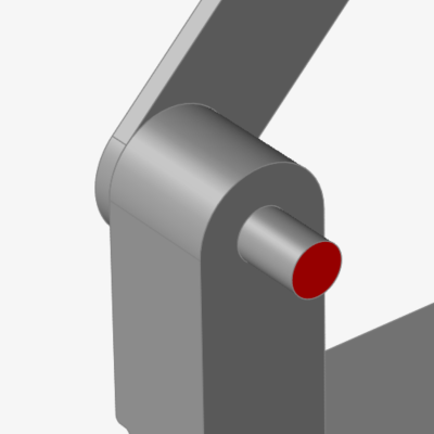
Click the Cen (center) snap point of the Link Crank part
to define the shaft connection point.
The feature turns red.
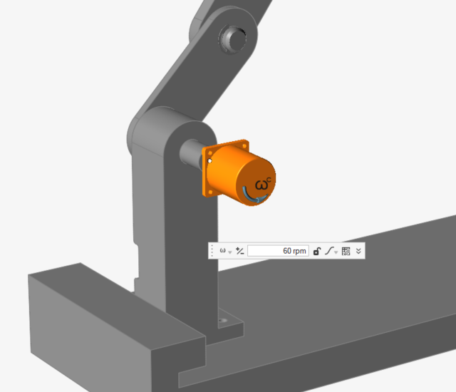
Select the Mount Crank as the base connection.
The motor is created, and a microdialog appears with the Speed set to 60
rpm.
Right-click and mouse through the check mark to exit, or double-right-click.
Add a Spring-Damper Force
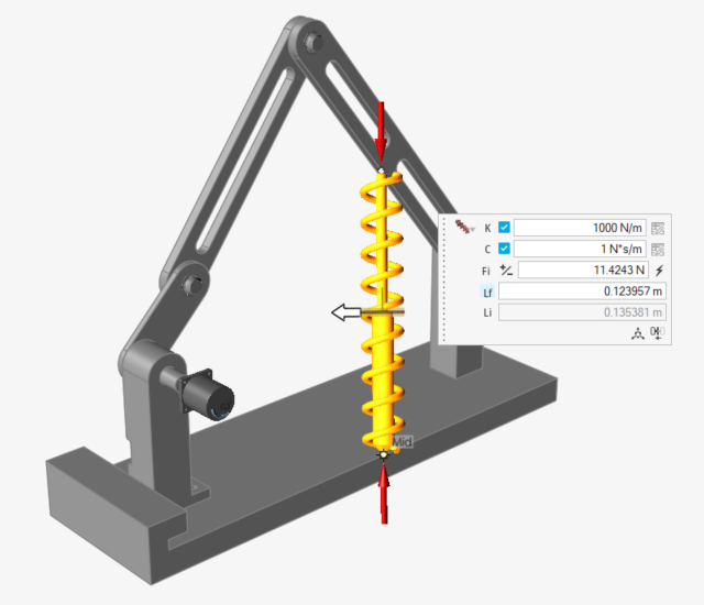
Select the Coil Spring tool.
Select the Link Dual Slot part.
Select the Base part.
Click the Mid (middle) edge snap point of the
Link Dual Slot part.
The selected feature turns red.Figure 4.
Click the Mid (middle) edge snap point of the
Base part.
Figure 5.
Click Accept to create
the spring.
A coil spring appears and the microdialog shows the default
settings.
In the microdialog that appears, change the K stiffness
value to 2500 N/m and C Damping to
1 N*s/m. Leave the Force and
Length options as the defaults.
Figure 6.
Click and drag the white arrow manipulator to reduce the spring diameter to
.01 m.
Right-click and mouse through the check mark to exit, or double-right-click.
Change the Run Settings and Rerun the Analysis
Click the Run Settings icon.
Change the End Time to 2 s by entering the value in the
field or clicking the 2 button.
Close the window.
Click the Quick Run button, then click
Continue on the Redundant Constraint message dialog,
to see movement of the model.
After two seconds, the run will complete and you will automatically be placed
into the Review Motion Results tool.
Optional: Click the Play button on the animation toolbar
to review the results.
Left-click and swipe to exit the animation context.
Review the Motion Analysis Results
Change the Time on the animation toolbar to
0.73 s by dragging the slider bar.
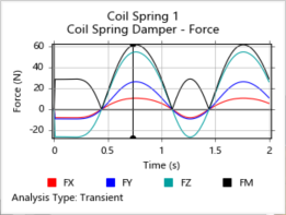
Select Coil Spring 1 in the modeling window to see a
plot of the spring forces.
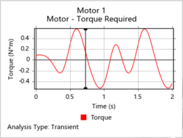
Select Motor 1 to see a plot of the motor's
output.
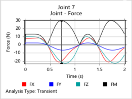
Click on the pin connecting the Link Single Slot to the Link Dual Slot to view
a plot for the pin.
Note: Right-click on the plot to view other components that can be
plotted.
Right-click and mouse through the check mark to exit, or double-right-click.


 changes to indicate that it is a ground part.
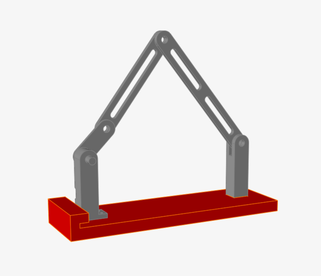


 icon appears and you are automatically placed into
review mode. Click the Review Motion Results icon or
double-right-click to exit review mode.
icon appears and you are automatically placed into
review mode. Click the Review Motion Results icon or
double-right-click to exit review mode.


 , then the
  button.


 to create
the spring.
A coil spring appears and the microdialog shows the default settings.
to create
the spring.
A coil spring appears and the microdialog shows the default settings.