Tutorial: Actuators and Analysis Types
Add an actuator to a motion model, then run transient and static motion analyses.
In this lesson you will learn how to:
- Ground a part
- Connect parts with joints
- Add an actuator to the model
- Determine the direction of gravity
- Run transient and statics motion analyses
- View and plot the results
Open the CAD model
- Press F7 to open the Demo Browser.
- Double-click the M05_LiftTable.x_t file in the Motion folder to load it in the modeling window.
- If not already visible, press F2 to open the Model Browser.
- Check that the display units are set to MPA.
Ground a Part
-
On the Motion ribbon, select the
Ground tool from the Connections category.

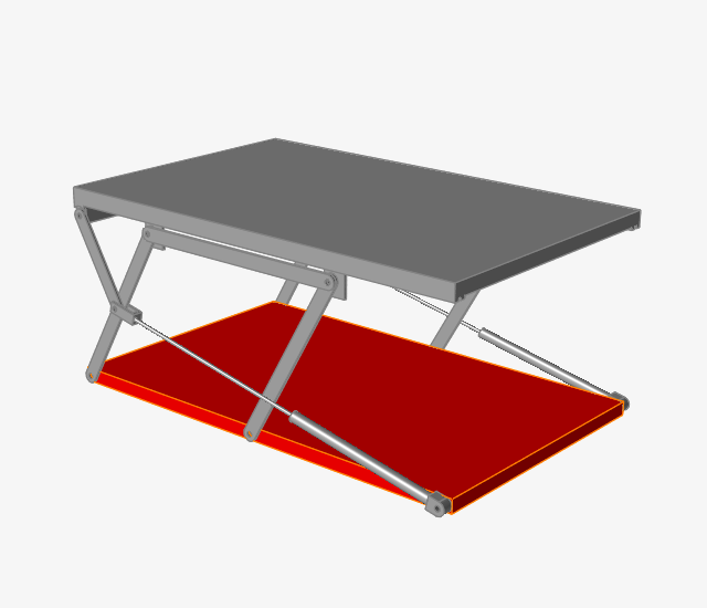
Tip: To find and open a tool, press Ctrl+F. For more information, see Find and Search for Tools. - Select the Base part to ground it.
-
The part turns red, and the part icon in the Model Browser
 changes to indicate that it is a ground part.
- Right-click and mouse through the check mark to exit, or double-right-click.
Connect Parts Together with Joints
-
Select the Joints tool.

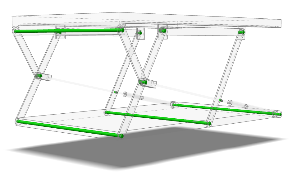
The guide bar appears with default settings (All Parts, All, Auto). -
Click
 , then the
  button on the guide bar.
Notice that joints are created at neighboring parts in the model, with colors used to indicate the joint state.
- Right-click and mouse through the check mark to exit, or double-right-click.
Add an Actuator to Drive the Mechanism
-
Select the Actuators tool.

-
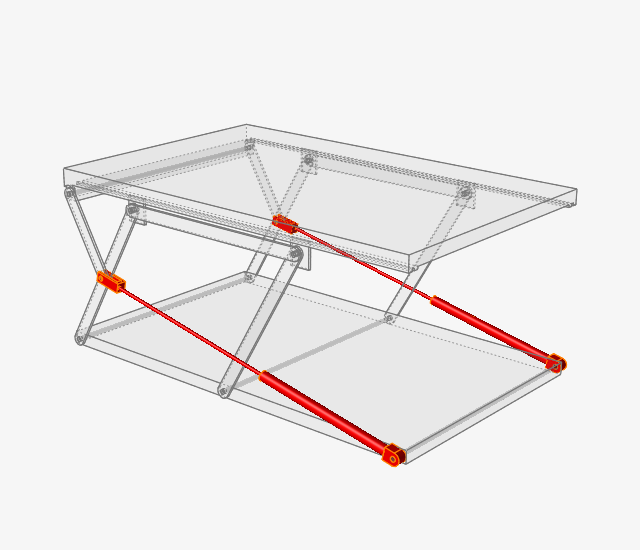
Select Connected Parts on the guide bar.
Candidate locations are shown in red.
-
Click on the right cylinder part of the mechanism.
The right cylinder and the right cylinder piston together become the actuator, which is represented by an arrow.
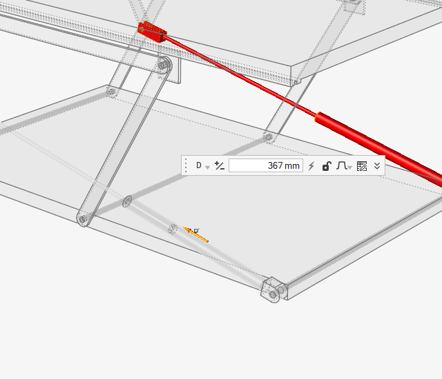
- From the actuator microdialog, change the magnitude of the displacement to 300 mm.
-
With the Actuator tool still active, box select the left
cylinder.
The left cylinder and the left cylinder system together become the actuator with the same attributes as that of the right cylinder and the right cylinder piston.
- Right-click and mouse through the check mark to exit, or double-right-click.
Inspect the Gravity Direction
-
Open the Gravity tool:
-
Notice that a vector is displayed which indicates the direction of
gravity.
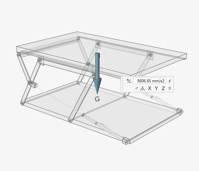
- Right-click and mouse through the check mark to exit, or double-right-click.
Change the Analysis Type to Statics
-
Hover over the Analyze Motion tool, then click the Run
Settings icon to open the Run Motion Analysis window.

-
Change the End Time to 2 s and
select the Statics option.
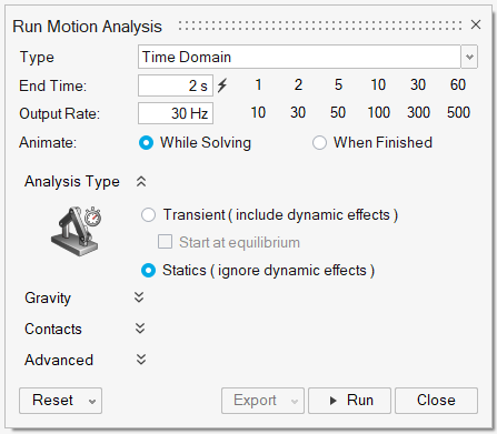
- Close the Run Motion Analysis window.
Run a Motion Analysis and Plot the Statics Analysis Results
-
Click the Quick Run button on the Analyze Motion tool to
see the model in motion, and let the model run to completion.

Note: Notice that the table first moves up and then down because of the actuators. -
When the analysis is complete, review mode is invoked automatically.
The run icon on the ribbon changes to review mode, and the animation toolbar appears at the bottom of the modeling window.

-
Select Actuator 2 in the modeling window by clicking the arrow glyph to see a
plot of the actuator force required.
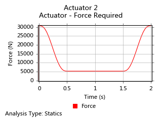
Note: When selecting the actuator, move your mouse cursor over the actuator arrow and wait for it to prehighlight blue before you click it. If you have trouble clicking on the actuator directly, try selecting it in the Model Browser. -
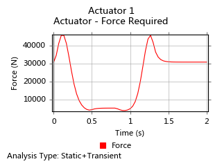
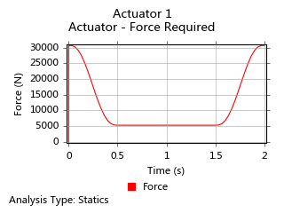
Select Actuator 1 in the modeling window by clicking the
arrow glyph to see a plot of the actuator force required.
Change the Analysis Type to Transient
-
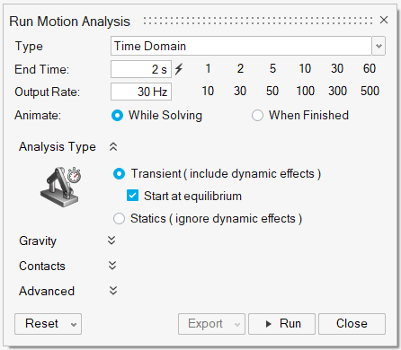
Click the Run Settings icon to open the Run Motion
Analysis window.

-
Select the Transient option and enable Start
at equilibrium.
The analysis will find the initial static equilibrium position before starting the transient simulation.
- Close the Run Motion Analysis window.
Run a Second Motion Analysis and Plot the Transient Results
-
Click the Quick Run button on the Analyze Motion tool to
see the model in motion, and let the model run to completion.

-
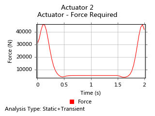
Select Actuator 2 in the modeling window or Model
Browser to see a plot of the actuator force required.
-
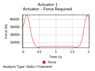
Select Actuator 1 in the modeling window or Model
Browser to see a plot of the actuator force required.
- Double-right-click to exit review mode.
Change the Dwell Time for the Actuator Function
- If not already visible, press F2 to open the Model Browser and F3 to open the Property Editor.
- Click in the Model Browser and scroll down to the actuators.
- Hold down the Shift key and select Actuator 1 and Actuator 2 in the Model Browser.
-
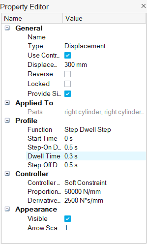
Change the Dwell Time to 0.3
seconds in the Property Editor under the Profile tab.
Change the Analysis Type Back to Statics Analysis
-
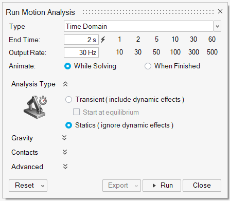
Click the Run Settings icon to open the Run Motion
Analysis window.

-
Select the Statics option.
- Close the Run Motion Analysis window.
Run a Third Motion Analysis and Plot the Statics Results
-
Click the Quick Run button on the Analyze Motion tool to
see the model in motion, and let the analysis run to completion.

-
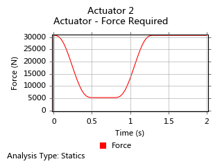
Select Actuator 2 in the modeling window or Model
Browser to see a plot of the actuator force required.
-
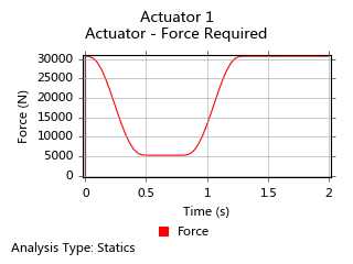
Select Actuator 1 in the modeling window or Model
Browser to see a plot of the actuator force required.
Change the Analysis Type Back to Transient Analysis
-
Click the Run Settings icon to open the Run Motion
Analysis window.

-
Select the Transient option and enable Start
at equilibrium.
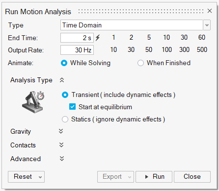
- Close the Run Motion Analysis window.
Run a Fourth Motion Analysis and Plot the Transient Results
-
Click the Quick Run button on the Analyze Motion tool to
see the model in motion, and let the analysis run to completion.

-
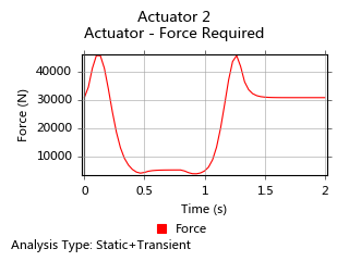
Select Actuator 2 from the Model Browser to see a plot
of the actuator force required.
-
Select Actuator 1 from the Model Browser to see a plot
of the actuator force required.
