Configure the settings and create a structural analysis report. You can save the
settings so they can be used for quick reports.
First, run a structural analysis.
-
On the Structures ribbon, select Report Settings.

The Report Settings dialog box is displayed.
-
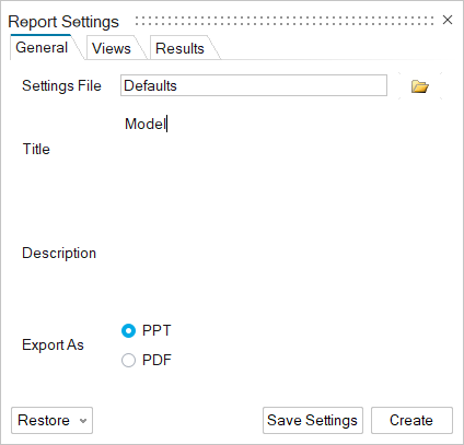
On the General tab:
-
Choose a Settings File:
- Defaults: By default, the report includes
the following:
- the report title (the model name)
- the description (left blank)
- an image of the model in the current view
- an image of the model in the ISO view
- the first load case
- the first result type
- Click the file icon to Import a Settings
File.
Tip: To
save a settings file:
- Select the Report Settings
tool.
- Configure the settings as desired.
- Click the Save Settings
button.
- Browse to the desired folder.
- Enter the file name.
- Click Save.
To use a saved report settings file:
- Click the Restore button.
- Select the desired settings file.
-
Enter the Title and
Description.
The report title appears on the first slide (front cover), while the
report description appears on the second slide first page).
-
Choose a format to Export As:
-
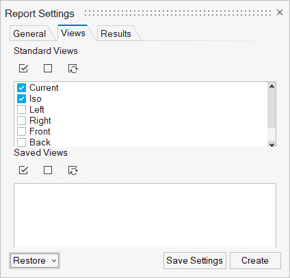
On the Views tab:
-
Select which views you want images of your models to be displayed in
the report.
- Standard Views: Select a standard view
for displaying the model on the front cover of the report.
- Saved Views: You can save scenes in a
.stmod file using the View tool and use these for capturing
hotspot views of the model for specific load cases.
-
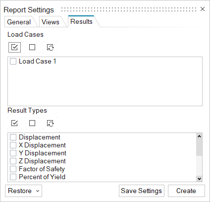
On the Results tab:
-
Select the Load Cases to include in the
report.
-
Select the Result Types to include in the
report.
-
To restore the default or custom settings, click Restore
and select the desired choice. By default, the report title is the model name;
the description is left blank; and an image of the model in ISO view, the first
load case, and the first result type are included in the report.
- Optional:
To save the current settings, which will be used for quick reports, click
Save Settings.
-
Click Create.
-
Browse to the location where you want to save the file. The default location is
C:\Documents\Altair\reports.
-
Enter the file name.
- Optional:
Choose a file format:
-
Click Save.