/INTER/SUB
Block Format Keyword Defines a sub-interface. A sub-interface is a portion of (may include all of) an existing interface and is defined in order to output the forces applied by nodes of a specified node group on the segments of a specified surface (refer to Time Histories output for interfaces).
Format
| (1) | (2) | (3) | (4) | (5) | (6) | (7) | (8) | (9) | (10) |
|---|---|---|---|---|---|---|---|---|---|
| /INTER/SUB/sub_inter_ID | |||||||||
| sub_inter_title | |||||||||
| inter_ID | Main_ID1 | Second_ID | Main_ID2 | ||||||
Definition
| Field | Contents | SI Unit Example |
|---|---|---|
| sub_inter_ID | Sub interface identifier. (Integer, maximum 10 digits) |
|
| sub_inter_title | Sub interface title. (Character, maximum 100 characters) |
|
| inter_ID | Interface identifier.
(Integer) |
|
| Main_ID1 | Main identifier.
(Integer) |
|
| Second_ID | Secondary identifier.
Ignored if inter_ID = 0. (Integer) |
|
| Main_ID2 | Second main surface identifier. |
Comments
- Only interface TYPE7, TYPE10, TYPE11, TYPE19, TYPE24 and TYPE25 are available for defining sub-interfaces.
- A hierarchy of sub-interfaces is not permitted.
- An interface and a sub-interface cannot have the same identifier.
- For sub-interfaces of TYPE7 TYPE10, TYPE11, TYPE19 and TYPE24:
All nodes defined by Second_ID should belong to the secondary nodes group of the interface.
All segments of the specified main surface or main line in the sub interface should belong to the main surface or main line of the interface.
All segments of the specified secondary surface or secondary line in the sub interface should belong to the secondary surface or secondary line of the interface.
- For sub-interfaces of a TYPE19 interface,
if Second_ID = 0, the sub-interface is symmetric and
Main_ID is also used as secondary surface.
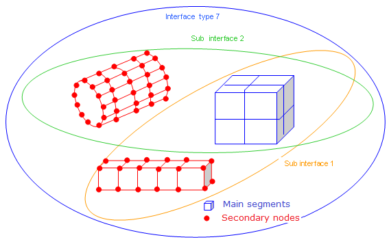
Figure 1. - For sub-interfaces of a TYPE25
interface:
If Second_ID ≠ 0, the forces applied by the secondary node group onto both main surfaces are considered.
If Main_ID2 ≠ 0, the forces applied by Main_ID1 onto Main_ID2 and vice versa are calculated.
- When inter_ID =
0, the force output in the TH file is the sum of all contact forces
from contacts acting on certain main segments, Second_ID is
ignored:
If Main_ID1 = 0, Main_ID2 > 0: the output is the sum of all contact forces, for segments in Main_ID2 surface sets.
If Main_ID1 > 0, Main_ID2 > 0: the output is the sum of all contact forces, between segments in Main_ID1 and Main_ID2 surface sets.