
OS-V: 0840 Viscoplastic Anand Material Model
Knowledge of the material model and its parameters is essential to predict the behavior of the printed components for FEM Analysis. Anand is one of the material models used to study viscoplastic materials.
To analyze the rate-dependent deformation of metals at high temperatures, the Anand model was suggested. The model applies to a wide range of viscoplastic problems, including the influence of the strain rate and temperature.
Model Files
Benchmark Model
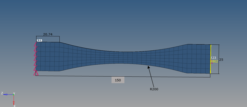
On one side of the specimen, all the nodes are constrained to three degrees of freedom (123).
Additionally, on the other side, RBE2 is applied on the entire phase and the center of the RBE2 element is constrained to three degrees of freedom (123), along with constraint 1 DOF (1) using the SPCD entry.
Units: mm, s, Mg, N, MPa
Material
The MAT1 Bulk Data Entry is used to input material data for the model.
The Poisson’s ratio ‘υ’ is defined on the NU field. Similarly, Young's Modulus and Density are defined in the E and RHO fields, respectively.
The Anand material model is assigned through MATVP. The CTYPE field on the MATVP entry is used to identify the creep material model type. Specifying a MAT1 and a MATVP Bulk Data Entry with the same MID allows modeling creep material.
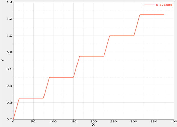
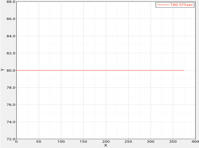
Temperature load is applied to the component.
The DLOAD Bulk Data Entry is used to give a dynamic loading condition for the load sets defined on the TLOAD1 entry.
With the obtained final parameter values of the Anand material model, the simulations were performed for a graded tensile test at 80 degrees Celsius.
Results
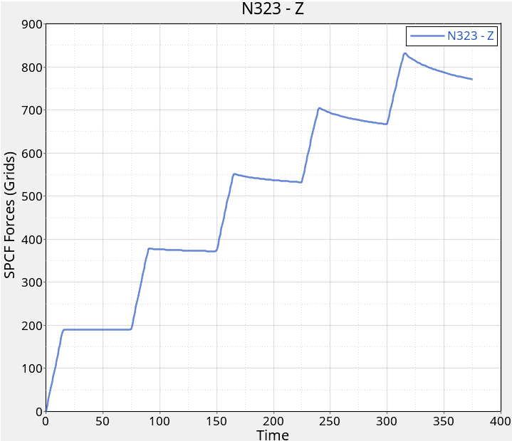
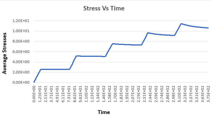
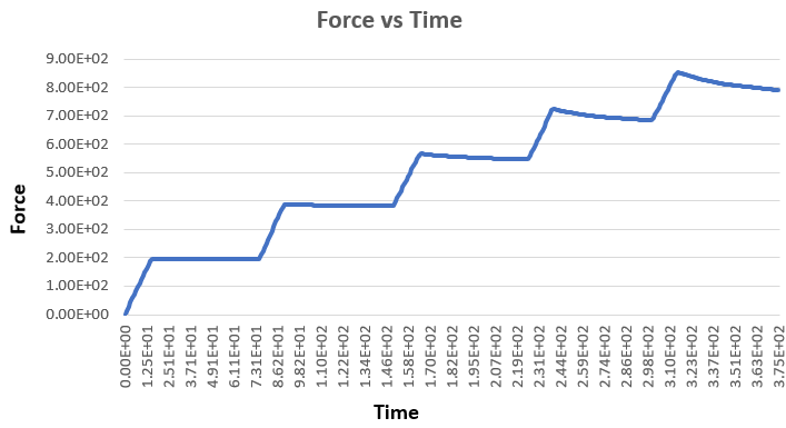
Since Force, as an output, is not supported for solid elements, average True zz stresses at the cross-section of the specimen, along with the dynamically changing area at each timestep are used to manually calculate the force.