
OS-V: 0350 Simply-Supported Thin Square Plate Periodic Forced Vibration Response
Test 13P OptiStruct is used to investigate the Peak Displacement in z-direction and extreme fiber bending stress at the center of the plate.
Model Files
Benchmark Model
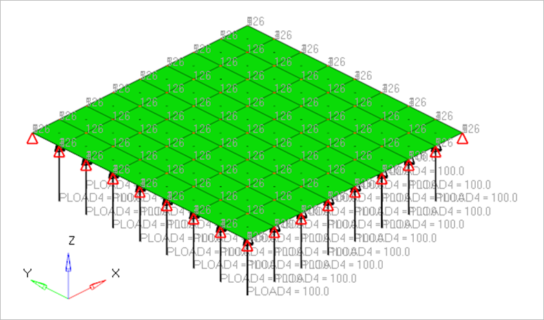
The 2nd order and 1st order quad elements are used to model the square plate of thickness 0.05 m. The z-rotation and x, y translations are fixed for all the nodes, z-translation is fixed along all four edges, x-rotation is fixed along the edge x = 0 and x = 10 and y-rotation is fixed along the edge y = 0 and y = 10. A steady-state harmonic forced vibration F = F0 (sin ωt-sin 3ωt) is induced in the z-direction. (F0 = 100 N/m2 over whole plate, ω = 2πf, f = 1.2 Hz). For modal analysis solution, a damping ratio of 0.02 is applied in all 16 modes and for direct solution, Rayleigh damping factor α1 = 0.299 and α2 = 1.339×10⁻³ are given.
- Material Properties
- Value
- Young’s Modulus
- 200 × 109 N/m2
- Poisson’s Ratio
- 0.3
- Density
- 8000 kg/m3
Frequency Response Summary
f*- Closed form solution
| Peak Displacement (mm) | Peak Stress (N/mm2) | |
|---|---|---|
| Reference Solution | 2.863 | 2.018 |
| HOE: | ||
| Direct Solution | 2.928 | 2.418 |
| Normalized | 0.977800546 | 0.834574028 |
| Modal Solution | 2.929 | 2.426 |
| Normalized | 0.977466712 | 0.831821929 |
| LOE: | ||
| Direct Solution | 2.825 | 1.956 |
| Normalized | 1.013451327 | 1.031697342 |
| Modal Solution | 2.826 | 1.961 |
| Normalized | 1.013092711 | 1.029066803 |
Reference
NAFEMS R0016 - Selected Benchmarks for Forced Vibration, J Maguire, D J, Dawswell, L Gould 1989