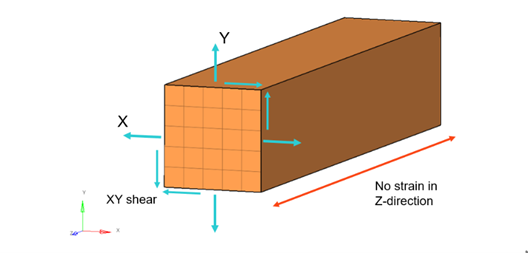
When running a CAE analysis, using the plane strain assumption can lead to
considerable savings in computational time and file storage. The simplification to a
2D mesh allows you to use a finer mesh resulting in a more accurate analysis than a
coarsely 3D meshed full model. A typical example of plane strain application is for
the analysis of pressure vessels.
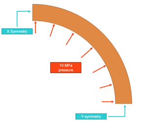
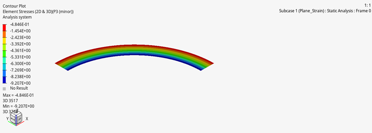
The following example examines the expansion of a pressure vessel due to internal
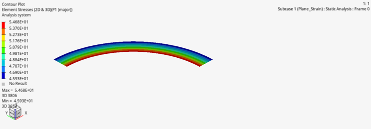
pressure. The OptiStruct results for principal stresses
and the theoretical values for principal stresses are compared.Figure 2. Model
Benchmark Model
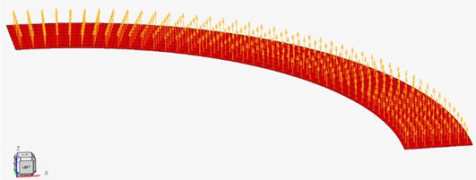
Plane Strain elements are used to model the quarter symmetric slice of the pressure
vessel with a radius of 100 mm and thickness of 20 mm. The internal pressure of 10
MPa is applied on the nodes of the inner surface of the pressure vessel and a Linear
Static analysis is performed.
The following is required for model setup:
The model must be in the XY or XZ plane, meaning for the XY plane all nodes
must have Z coordinates equal to zero and for the XZ plane all Y coordinates
are zero.
All element normals are pointed in the positive Z or Y direction.Figure 3.
CTPSTN and CQPSTN are used as the
element property.
PPLANE is used as the card image for the property.
The 10 MPa load is applied using PLOADE1 type and
selecting the internal edge of the model.
For thick-walled cylinders, stresses can be expressed as:
Circumferential Direction - Hoop Stress
Radial Direction
Where,
Stress in circumferential direction (MPa, psi).
Stress in radial direction (MPa, psi).
Internal pressure in the tube or cylinder (MPa, psi).
External pressure in the tube or cylinder (MPa, psi).
Internal radius of tube or cylinder (mm, in).
External radius of tube or cylinder (mm, in).
Cylinder wall radius where stress is calculated (mm, in) ( < < ).