MV-7012: Functional Mockup Unit (FMU) in MotionView and MotionSolve
Tutorial Level: Advanced In this tutorial, you will learn about the use of FMU in MotionView and MotionSolve.
Functional Mock-up Interface (FMI) is a tool independent standard interface that facilitates exchange of models across diverse domains and applications. Based on this interface, a Functional Mock-up Unit (FMU) describing the model using a combination of xml-files, compiled C-code and other resource files can be shared and used in applications that supports such an interface.
- Model Exchange
- The FMU contains the necessary information about states. The parent application that uses this FMU “internalizes” and solves for these states.
- Co-simulation
- The FMU either includes the solver or can connect to an external solver. In this case, the parent application co-simulates along with the FMU or the external solver.
Two versions of the FMI, FMI 1.0 and FMI 2.0, are used today. MotionView and MotionSolve support only FMI 2.0. For additional details on how to use FMU in MotionView, refer to the MDL Reference Guide and the MotionSolve Reference Guide.
This tutorial will describe the steps required to:
- Open and review the swing-up pendulum model
- Add an FMU in MotionView
- Connect input and output to the FMU
- Run the model and view the results
In this tutorial, a pendulum is balanced on a cart, which can slide on a fixed platform. The bob of the pendulum faces down at the beginning of the simulation; the goal is to move the cart and swing the pendulum so that the bob faces upward. Once it achieves this position, it also needs to be maintained in the same position.
To achieve this objective, a controller unit in form of an FMU is used to determine the force necessary to balance the pendulum. The FMU is generated independently from a different control system modeling application.
Open and Review the Swing-up Pendulum Model
-
Click
 and open the model
Swingup_pendulum_FMU_start.mdl in MotionView.
and open the model
Swingup_pendulum_FMU_start.mdl in MotionView.
-
Review the bodies, joints and force defined in the model.
Figure 1. Swing-up pendulum setup 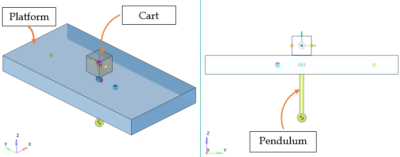
The swing-up pendulum model consists of four bodies:Body Name Variable Name Ground Body B_GroundPendulum b_linkCart b_cartPlatform b_platThey are connected to each other by the following three joints:Joint Name Variable Name Joint Type Body 1 Body 2 Fix Platform to Ground j_ground_platFixed Platform Ground Body Pin Pendulum to Cart j_pend_cartRevolute Pendulum Cart Cart to Platform j_plat_cartTranslation Cart Platform A control force 'Force on Cart' is applied with its value being zero at this point.The bob of the pendulum is facing downward in the initial configuration. The objective of the simulation is to exert a control force in the Y direction, so that the cart moves and the pendulum swings to a position where the bob faces upwards. The control force should maintain this position once achieved.
In this tutorial an FMU is added and the displacement of cart, angle and rotational velocity of pendulum are provided as inputs to the FMU. The output of the FMU will be connected to 'Force on Cart' in the Y direction to generate the required movement of the cart to balance the pendulum. The simulation is performed using MotionSolve to see the effect of the controller.
Add an FMU
-
Add the FMU entity to the system by any of the following methods:
- Right-click on the FMU icon
 on the Control toolbar.
 - Right-click on the system in the Project Browser and
select Add > Control Entity > FMU from the context menu.
- Right-click on any existing FMU folder in the Project Browser and select Add FMU… from the context
menu.
The Add FMU dialog is displayed. - Right-click on the FMU icon
- Retain the default label and a variable name.
-
Use the File browser
 to locate and select the
sb_Controller.fmu file. Click
Open.
to locate and select the
sb_Controller.fmu file. Click
Open.
-
Click OK to add the entity.
Figure 2. Panel after adding FMU 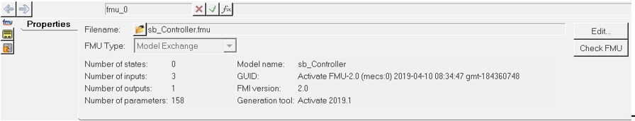
As shown in the panel, the ‘Model Exchange’ FMU type accepts three inputs and provides one output.The panel also provides additional information, such as the Generation tool, that shows the application from which the FMU originated.
-
Click Check FMU to run the compliance check on the FMU.
The compliance tool validates the FMU and reports any warnings or errors.
Note: MotionView also executes Check FMU when checking a model and during export to the solver.Generally, any initial condition of the FMU model exposed for change is available as a parameter. For this exercise, no change in the initial conditions is needed for the controller, therefore the parameters can be ignored.
Connect Input and Output to the FMU
-
Click on Edit... to view and edit the FMU.
The FMU dialog appears which contains Inputs, Outputs, Parameters and Settings tabs.
-
From the Inputs tab, enter the following expressions
under the Value column against each input as
follows:
Input # Name Expression Details 1 Angle (rad)
Pendulum Joint Angle 2 Angular Velocity
(rad/s)
Rotational Velocity of Pendulum 3 Position (mm)

Cart Displacement in the Y direction with regard to Platform Note: The expressions can be built using the Expression Builder (fx) available at the top of the panel. - Go to the Outputs tab and Review the single output “Control Force” listed.
- Click OK to close the dialog box.
- Select the Force on Cart force entity.
- Click on the Trans Properties tab.
- For Fy, use the drop-down menu to select Expression.
-
Click the fx button at the top of the panel to display
the Expression Builder.
Figure 3. 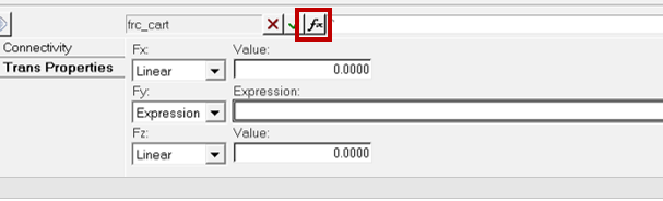
-
In the Expression Builder, expand the model tree below to access the
Output Array attribute of the FMU. Select the child
attribute output_1 and add it to the expression between
the curly braces '{}'.
Figure 4. Selecting output from the Expression Builder 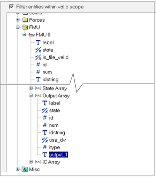
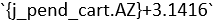
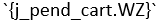
Note: The output array will contain the number of output attributes equal to the number of outputs in the FMU;output_1refers to 1st output,output_2refers to 2nd output, and so on.The expression in the Expression Builder should look as below:Figure 5. Expression for the Force 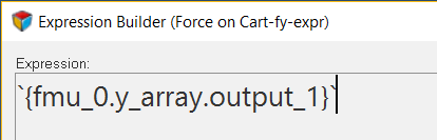
-
Click OK to close the Expression Builder.
The above expression evaluates to the solver function ARYVAL, that returns the value of a particular index of an array. In this case, the ARYVAL function gives the value of the 1st index of the output array used by the FMU.
The inputs and output are now defined for the FMU.
-
Use Check Model
 to check the model for errors.
-
Click
 and save the model as
Swingup_pendulum_FMU.mdl.
and save the model as
Swingup_pendulum_FMU.mdl.
Run the Model and Review the Results
-
Go to the Run panel
 .
The default settings and value can be retained.
.
The default settings and value can be retained. - Click on the Run button to start the simulation.
- Once the run is complete, close the solver window.
- Click the Animate button to load the result in HyperView.
-
Once the H3D file is loaded in HyperView, click the
Start/Pause Animation button
 to view the animation.
If the simulation has run correctly, the force exerted by the controller would swing the bob upwards and continue to balance it for the rest of the time.
to view the animation.
If the simulation has run correctly, the force exerted by the controller would swing the bob upwards and continue to balance it for the rest of the time.Figure 6. Path taken by the bob to reach the upright position 
-
Use the Plot button in the MotionView Run panel to plot the cart position and the
force on the cart using the following Type-Request-Component on the Y
axis:
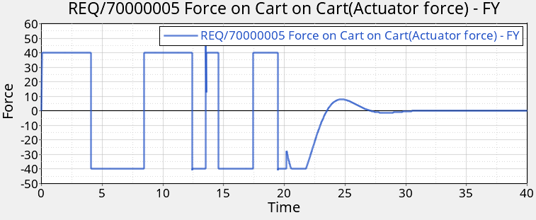
Y Type Y Request Y Component Marker Displacement REQ/70000002 Cart(Disp cart) DY Marker Force REQ/70000005 Force on Cart on Cart(Actuator force) FY Figure 7. Cart displacement 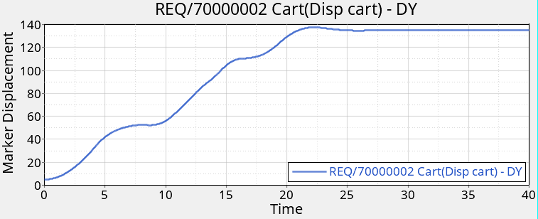
Figure 8. Actuator force