MV-1027: Model a Point-to-Deformable-Curve (PTdCV) Higher-Pair Constraint
Tutorial Level: Advanced In this tutorial, you will learn how to model a PTdCV joint (point-to-deformatble-curve) joint.
Create Points
In this step you will create the points for the PTdCV model.
- Start a new MotionView session.
-
Open the Add Point or PointPair dialog in one of the
following ways:
- From the Project Browser right-click on Model and select .
- On the Model-Reference toolbar, right-click the
 (Point) icon.
- For Label, enter PointbeamInterface1. Accept the default Variable name.
- Click OK.
- Click the Properties tab and specify the the coordinates as X = 152.4, Y = 0.0, and Z = 0.0.
-
Repeat steps 2
through 5 for the
points specified in Table 1.
Table 1. Point X Y Z PointbeamInterface2 460.80 0.0 0.0 Point0 183.24 0.0 0.0 Point1 214.08 0.0 0.0 Point2 244.92 0.0 0.0 Point3 275.76 0.0 0.0 Point4 306.60 0.0 0.0 Point5 337.44 0.0 0.0 Point6 368.28 0.0 0.0 Point7 399.12 0.0 0.0 Point8 429.96 0.0 0.0
Create Bodies
In this step you will create the bodies for the PTdCV model.
-
Open the Add Body or BodyPair dialog in one of the
following ways:
- From the Project Browser right-click on Model and select .
- On the Model-Reference toolbar, right-click on the
 (Body) icon.
-
In the dialog, for Label enter Beam. Accept the default
Variable name and click OK.
Note: For the remainder of the tutorial, accept all default variable names.
- From the Properties tab, click the Flex Body (CMS) check box.
-
Click the
 (Graphic file browser) icon and select
KG_N_MM_S_50elems2.h3d from the <working
directory>.
Note: The same file path with automatically populate the H3D file field.
(Graphic file browser) icon and select
KG_N_MM_S_50elems2.h3d from the <working
directory>.
Note: The same file path with automatically populate the H3D file field. - Repeat step 1. In the dialog, for Label enter Ball and click OK.
-
From the Properties tab:
- Clear the Get Properties from associated Graphic(s) check box.
- Specify the information given in Table 2.
Table 2. Mass Ixx Iyy Izz Ixy Iyz Izx 100 1e6 1e6 1e6 0.0 0.0 0.0 - Under the CM Coordinates tab, check the Use center of mass coordinate system box.
-
Double click
 .
.
- From the dialog, select Point4 and click OK. Accept defaults for axes orientation properties.
- In the Initial Conditions tab, under Translational velocity check the Vx box.
-
In the text box, enter a value of 100. Accept all other
default values.
This sets a value of 100 for the translational velocity of the ball in the X-direction. A somewhat high value of Vx is introduced to make the motion of the ball clearly visible in the animation.
Create Markers
In this step you will define the markers required for the beam.
-
Open the Add Marker or MarkerPair dialog in one of the
following ways:
- From the Project Browser, right-click on Model and select .
- On the Model-Reference toolbar, click the
 (Marker) icon.
- In the dialog, for Label enter Marker0 and click OK.
-
In the Properties tab, double-click
 .
.
- In the dialog, choose Beam and click OK.
-
Double-click .
-
In the dialog, choose PointbeamInterface1 and click
OK.
Accept the default for axes orientation.
-
Repeat steps 1
through 6 for the
points specified in Table 3.
Table 3. Name Body Point Marker0 Beam PointbeamInterface1 Marker1 Beam Point0 Marker2 Beam Point1 Marker3 Beam Point2 Marker4 Beam Point3 Marker5 Beam Point4 Marker6 Beam Point5 Marker7 Beam Point6 Marker8 Beam Point7 Marker9 Beam Point8 Marker10 Beam Pointbeaminterface2
Create Joints
In this step you will define the fixed joints necessary for the model.
-
Open the Add Joint or JointPair dialog in one of the
following ways:
- From the Project Browser, right-click on Model and select .
- On the Model-Constraints toolbar, click the
 (Joints) icon.
- In the dialog, for Label enter Joint0.
- In the drop-down-menu, select Fixed Joint and click OK.
-
In the panel, double-click
 .
.
- In the dialog, choose Beam and click OK.
-
Double-click
 .
.
- In the dialog, select Ground Body and click OK.
-
Double-click .
- In the dialog, select PointbeamInterface1 and click OK.
-
Repeat steps 1
through 9 to
create a second fixed joint.
- For Label, enter Joint1.
-
For , choose
PointbeamInterface2.
- For all other steps, use the same inputs as you did for Joint0.
Create Deformable Curves
In this step you will define a deformable curve on the surface of the beam.
-
Open the Add DeformableCurve dialog by doing one of the
following:
- From the Project Browser, right-click on Model and select .
- On the Model-Reference toolbar, click the
 (Deformable Curve)
icon.
(Deformable Curve)
icon.
- In the dialog, for Label enter DeformableCurve0.
- Click OK.
-
In the Properties tab, specify the properties of the deformable curve.
-
Click the check box next to
 .
The Add button will change to an Insert button.
.
The Add button will change to an Insert button. -
In the text box next to Insert, enter 10. Then
click Insert.
Eleven collectors will display in the
panel.
-
Double-click on each individually.
-
Click the check box next to
Create the PTdCV Joint
In this step you will create the advanced PTdCV joint.
-
Open the Add AdvJoint dialog by doing one of the
following:
- From the Project Browser, right-click on Model and select .
- On the Model-Reference toolbar, click the
 (Advanced Joint)
icon.
(Advanced Joint)
icon.
- In the dialog, for Label enter AdvancedJoint 0.
-
In the Connectivity tab, specify the connections shown below.
PointToDeformableCurveJoint, Ball for Body, Point4 for Point, and DeformableCurve 0 for DeformableCurve.
Create Graphics
In this step, you will create a graphic for the ball.
-
Open the Add Graphics or GraphicPair dialog in one of the
following ways:
- From the Project Browser, right-click on Model and select .
- On the Model-Reference toolbar, click the
 (Graphics) icon.
- In the dialog, for Label enter Graphic0.
- In the Type drop-down menu, choose Sphere. Then click OK.
-
In the Connectivity tab, double-click .
- In the dialog, select Ball and click OK.
-
Double-click on .
- In the dialog, select Point4 and click OK.
- In the Properties tab, under Radius enter 2.0.
- In the Visualization tab, choose a color for the graphic.
Find Nodes
In this step, you will return to the Bodies Panel and find the Nodes on the beam.
- In the Project Browser, click on the Beam body.
-
On the reference toolbar, click the (Bodies) icon.
- In the panel, click the Nodes button.
- In the dialog, uncheck the Only search interface nodes box.
- Click the Find All button.
-
Close the dialog.
Your model should resemble the example shown in Figure 1.
Figure 1. 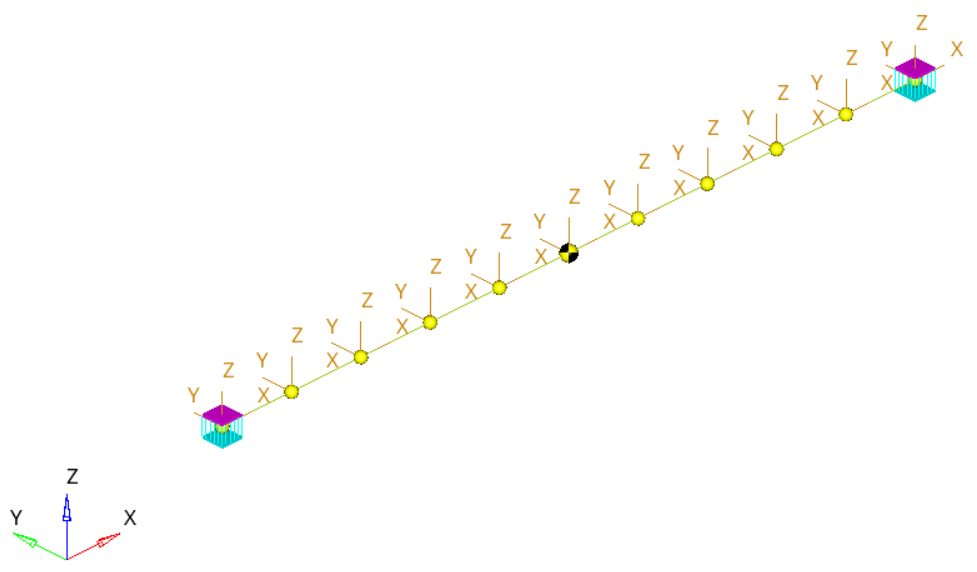
Run the Model
In this step you will run the model with the PTdCV joint constraint.
-
On the toolbar, click
 (Run).
-
In the Run panel, specify the values shown in Figure 2.
Figure 2. 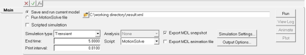
- Click the Save and run current model radio button.
-
Click the
 (browser icon) and specify a name for the solver
file.
(browser icon) and specify a name for the solver
file.
- Click Save.
-
On the Model Check toolbar, click the
 (Check Model) button to check the model for
errors.
(Check Model) button to check the model for
errors.
- To invoke the solver, click the Run button.
-
Once the solver has finished, click the
 (Start/Pause Animation) button to view the
animation.
(Start/Pause Animation) button to view the
animation.
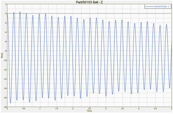
View the Results
In this step, you will plot the Z position of the center of mass of the ball.
-
Click on the
 (Add Page) icon.
-
In the Select application drop-down menu, change the client from MotionView
 to HyperGraph 2D
 .
.
-
On the Curves toolbar, click
 (Build Plots).
-
Click the (file browser) and open the
results.abf file.
-
Configure the Plots panel as show in Figure 3.
Figure 3. 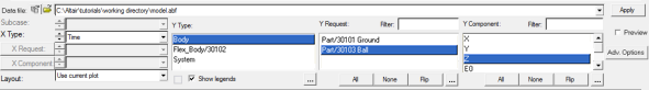
-
Click OK.
This will plot the Z-displacement of the ball. The plot should look like the example given in Figure 4.
Figure 4.