Version: December 2010 Edition
List of Classification Parameters
Evaluation Distance
Reference distance to find the evaluation location from the weld element at
which the stress values are extracted.
Weld Width
Width of the weld material from the web wall. This parameter is ignored if
specifying the evaluation distance is done manually.
Safety Factor (Gmf)
Used in calculation of the corrected weld detail category.
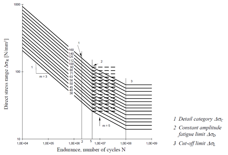
Fatigue Limit Slope - Normal Stress (Md)
Slope of the curve at the fatigue limit for normal stress components of
tensor. Refer to location 2 in the graph .
Fatigue Limit Slope - Shear Stress (Md)
Slope of the curve at the fatigue limit for shear stress components of
tensor. Refer to location 2 in the
graph .
Cutoff Limit Slope - Normal Stress (Ml)
Slope of the curve at the cutoff limit for normal stress components of
tensor. Refer to location 3 in the graph .
Cutoff Limit Slope - Shear Stress (Ml)
Slope of the curve at the cutoff limit for shear stress components of
tensor. Refer to location 3 in the graph .
Number of Cycles at Fatigue Limit (Nd)
Number of cycles in the S-N curve at the fatigue limit.
Number of Cycles at Cutoff Limit (Nd)
Number of cycles in the S-N curve at the cutoff limit.
Desired Cycles Detail From
Parameter that will show where HL-WC is reading
the desired number of cycles from.
Location Wise Parameters
Note: Where ‘X’ in the below parameters can be any evaluation location from 1-10.
Weld Detail Category - Transverse Location_X
Weld detail category from the image below that will be considered for the
calculation of fatigue and cutoff limits of the normal stress component in
the transverse direction (perpendicular to the axis of the weld) at
‘X’.
Weld Detail Category - Longitudinal Location_X
Weld detail category from the image below that will be considered for the
calculation of fatigue and cutoff limits of the normal stress component in
the longitudinal direction (parallel to the axis of the weld) at ‘X’.
Weld Detail Category - Shear Location_X
Weld detail category from the image below that will be considered for the
calculation of fatigue and cutoff limits of the shear stress component at
‘X’.
Material Yield - Location_X
Material yield value used for the static evaluation.
Figure 1 .
Symbols
Weld detail category (Normal) -
Δ
σ
c
MathType@MTEF@5@5@+=
feaahqart1ev3aaatCvAUfeBSjuyZL2yd9gzLbvyNv2CaerbuLwBLn
hiov2DGi1BTfMBaeXatLxBI9gBaerbd9wDYLwzYbItLDharqqtubsr
4rNCHbGeaGqiVu0Je9sqqrpepC0xbbL8F4rqqrFfpeea0xe9Lq=Jc9
vqaqpepm0xbba9pwe9Q8fs0=yqaqpepae9pg0FirpepeKkFr0xfr=x
fr=xb9adbaqaaeGaciGaaiaabeqaamaabaabaaGcbaGaeuiLdqKaeq
4Wdm3aaSbaaSqaaiaadogaaeqaaaaa@3A30@
Weld detail category (Shear) -
Δ
τ
c
MathType@MTEF@5@5@+=
feaahqart1ev3aaatCvAUfeBSjuyZL2yd9gzLbvyNv2CaerbuLwBLn
hiov2DGi1BTfMBaeXatLxBI9gBaerbd9wDYLwzYbItLDharqqtubsr
4rNCHbGeaGqiVu0Je9sqqrpepC0xbbL8F4rqqrFfpeea0xe9Lq=Jc9
vqaqpepm0xbba9pwe9Q8fs0=yqaqpepae9pg0FirpepeKkFr0xfr=x
fr=xb9adbaqaaeGaciGaaiaabeqaamaabaabaaGcbaGaeuiLdqeeaa
aaaaaaa8qacqaHepaDpaWaaSbaaSqaaiaadogaaeqaaaaa@3A61@
Safety factor for strength -
γ
M
f
MathType@MTEF@5@5@+=
feaahqart1ev3aaatCvAUfeBSjuyZL2yd9gzLbvyNv2CaerbuLwBLn
hiov2DGi1BTfMBaeXatLxBI9gBaerbd9wDYLwzYbItLDharqqtubsr
4rNCHbGeaGqiVu0Je9sqqrpepC0xbbL8F4rqqrFfpeea0xe9Lq=Jc9
vqaqpepm0xbba9pwe9Q8fs0=yqaqpepae9pg0FirpepeKkFr0xfr=x
fr=xb9adbaqaaeGaciGaaiaabeqaamaabaabaaGcbaaeaaaaaaaaa8
qacqaHZoWzpaWaaSbaaSqaaiaad2eacaWGMbaabeaaaaa@39B2@
Static Assessment
The following process is followed for Static assessment:
Retrieve the six components of stress from the element at the evaluation
location.
Calculate the von Mises stress value using these stress components.
Retrieve the material yield value from the Points context.
Determine the static strength ratio: element von Mises stress / material
yield value.
Formulation
Stress Component Considered for Evaluation
Δ
σ
T
MathType@MTEF@5@5@+=
feaahqart1ev3aaatCvAUfeBSjuyZL2yd9gzLbvyNv2CaerbuLwBLn
hiov2DGi1BTfMBaeXatLxBI9gBaerbd9wDYLwzYbItLDharqqtubsr
4rNCHbGeaGqiVu0Je9sqqrpepC0xbbL8F4rqqrFfpeea0xe9Lq=Jc9
vqaqpepm0xbba9pwe9Q8fs0=yqaqpepae9pg0FirpepeKkFr0xfr=x
fr=xb9adbaqaaeGaciGaaiaabeqaamaabaabaaGcbaGaeuiLdqKaeq
4Wdm3aaSbaaSqaaiaadsfaaeqaaaaa@3A21@
Δ
σ
L
MathType@MTEF@5@5@+=
feaahqart1ev3aaatCvAUfeBSjuyZL2yd9gzLbvyNv2CaerbuLwBLn
hiov2DGi1BTfMBaeXatLxBI9gBaerbd9wDYLwzYbItLDharqqtubsr
4rNCHbGeaGqiVu0Je9sqqrpepC0xbbL8F4rqqrFfpeea0xe9Lq=Jc9
vqaqpepm0xbba9pwe9Q8fs0=yqaqpepae9pg0FirpepeKkFr0xfr=x
fr=xb9adbaqaaeGaciGaaiaabeqaamaabaabaaGcbaGaeuiLdqKaeq
4Wdm3aaSbaaSqaaiaadYeaaeqaaaaa@3A19@
Δ τ
MathType@MTEF@5@5@+=
feaahqart1ev3aaatCvAUfeBSjuyZL2yd9gzLbvyNv2CaerbuLwBLn
hiov2DGi1BTfMBaeXatLxBI9gBaerbd9wDYLwzYbItLDharqqtubsr
4rNCHbGeaGqiVu0Je9sqqrpepC0xbbL8F4rqqrFfpeea0xe9Lq=Jc9
vqaqpepm0xbba9pwe9Q8fs0=yqaqpepae9pg0FirpepeKkFr0xfr=x
fr=xb9adbaqaaeGaciGaaiaabeqaamaabaabaaGcbaGaeuiLdqeeaa
aaaaaaa8qacqaHepaDaaa@393E@
Corrected Weld Detail Category
Δ
σ
c
( C o r r e c t e d ) =
Δ
σ
c , B a s i c
γ
M f
MathType@MTEF@5@5@+=
feaagKart1ev2aaatCvAUfeBSjuyZL2yd9gzLbvyNv2CaerbuLwBLn
hiov2DGi1BTfMBaeXatLxBI9gBaerbd9wDYLwzYbItLDharqqtubsr
4rNCHbGeaGqiVu0Je9sqqrpepC0xbbL8F4rqqrFfpeea0xe9Lq=Jc9
vqaqpepm0xbba9pwe9Q8fs0=yqaqpepae9pg0FirpepeKkFr0xfr=x
fr=xb9adbaqaaeGaciGaaiaabeqaamaabaabaaGcbaGaeuiLdqKaeq
4Wdm3aaSbaaSqaaiaadogaaeqaaOGaaiikaiaadoeacaWGVbGaamOC
aiaadkhacaWGLbGaam4yaiaadshacaWGLbGaamizaiaacMcacqGH9a
qpdaWcaaqaaiabfs5aejabeo8aZnaaBaaaleaacaWGJbGaaiilaiaa
dkeacaWGHbGaam4CaiaadMgacaWGJbaabeaaaOqaaiabeo7aNnaaBa
aaleaacaWGnbGaamOzaaqabaaaaaaa@51F6@
Where:
Δ
σ
c
,
B
a
s
i
c
MathType@MTEF@5@5@+=
feaagKart1ev2aaatCvAUfeBSjuyZL2yd9gzLbvyNv2CaerbuLwBLn
hiov2DGi1BTfMBaeXatLxBI9gBaerbd9wDYLwzYbItLDharqqtubsr
4rNCHbGeaGqiVu0Je9sqqrpepC0xbbL8F4rqqrFfpeea0xe9Lq=Jc9
vqaqpepm0xbba9pwe9Q8fs0=yqaqpepae9pg0FirpepeKkFr0xfr=x
fr=xb9adbaqaaeGaciGaaiaabeqaamaabaabaaGcbaGaeuiLdqKaeq
4Wdm3aaSbaaSqaaiaadogacaGGSaGaamOqaiaadggacaWGZbGaamyA
aiaadogaaeqaaaaa@3F5E@
- Weld detail category before correction. Note: The above formulas are for the normal component. Similar formulas
are applicable to other shear components as well.
Calculation of the Assessment Stress
In the case of Eurocode, stress range is used as assessment stress.
Δ σ ( S t r e s s R a n g e ) = (
σ
max
−
σ
min
)
MathType@MTEF@5@5@+=
feaagKart1ev2aaatCvAUfeBSjuyZL2yd9gzLbvyNv2CaerbuLwBLn
hiov2DGi1BTfMBaeXatLxBI9gBaerbd9wDYLwzYbItLDharqqtubsr
4rNCHbGeaGqiVu0Je9sqqrpepC0xbbL8F4rqqrFfpeea0xe9Lq=Jc9
vqaqpepm0xbba9pwe9Q8fs0=yqaqpepae9pg0FirpepeKkFr0xfr=x
fr=xb9adbaqaaeGaciGaaiaabeqaamaabaabaaGcbaGaeuiLdqKaeq
4WdmNaaiikaiaadofacaWG0bGaamOCaiaadwgacaWGZbGaam4Caiaa
ysW7caWGsbGaamyyaiaad6gacaWGNbGaamyzaiaacMcacqGH9aqpca
GGOaGaeq4Wdm3aaSbaaSqaaiGac2gacaGGHbGaaiiEaaqabaGccqGH
sislcqaHdpWCdaWgaaWcbaGaciyBaiaacMgacaGGUbaabeaakiaacM
caaaa@5311@
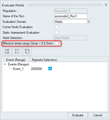
If effective stress range is enabled in evaluation to account for mean
stress influence on fatigue strength for non-welded and stress-relieved
welds, then stress range is calculated as shown below:
Δ σ ( E f f e c t i v e S t r e s s R a n g e ) = |
σ
max
| + 0.6 |
σ
min
|
MathType@MTEF@5@5@+=
feaahqart1ev3aaatCvAUfeBSjuyZL2yd9gzLbvyNv2CaerbuLwBLn
hiov2DGi1BTfMBaeXatLxBI9gBaerbd9wDYLwzYbItLDharqqtubsr
4rNCHbGeaGqiVu0Je9sqqrpepC0xbbL8F4rqqrFfpeea0xe9Lq=Jc9
vqaqpepm0xbba9pwe9Q8fs0=yqaqpepae9pg0FirpepeKkFr0xfr=x
fr=xb9adbaqaaeGaciGaaiaabeqaamaabaabaaGcbaGaeuiLdqKaeq
4WdmNaaiikaiaadweacaWGMbGaamOzaiaadwgacaWGJbGaamiDaiaa
dMgacaWG2bGaamyzaiaaysW7caWGtbGaamiDaiaadkhacaWGLbGaam
4CaiaadohacaaMe8UaamOuaiaadggacaWGUbGaam4zaiaadwgacaGG
PaGaeyypa0JaaGjbVlaacYhacaaMe8Uaeq4Wdm3aaSbaaSqaaiGac2
gacaGGHbGaaiiEaaqabaGccaaMe8UaaiiFaiabgUcaRiaaysW7caaI
WaGaaiOlaiaaiAdacaaMe8UaaiiFaiaaysW7cqaHdpWCdaWgaaWcba
GaciyBaiaacMgacaGGUbaabeaakiaaysW7caGG8baaaa@6C7C@
Figure 2 .
Fatigue Limit Calculation
(
Δ
σ
D
MathType@MTEF@5@5@+=
feaahqart1ev3aaatCvAUfeBSjuyZL2yd9gzLbvyNv2CaerbuLwBLn
hiov2DGi1BTfMBaeXatLxBI9gBaerbd9wDYLwzYbItLDharqqtubsr
4rNCHbGeaGqiVu0Je9sqqrpepC0xbbL8F4rqqrFfpeea0xe9Lq=Jc9
vqaqpepm0xbba9pwe9Q8fs0=yqaqpepae9pg0FirpepeKkFr0xfr=x
fr=xb9adbaqaaeGaciGaaiaabeqaamaabaabaaGcbaGaeuiLdqKaeq
4Wdm3aaSbaaSqaaiaadseaaeqaaaaa@3A11@
For Normal Component:
Δ
σ
D
= Δ
σ
c
·
(
2 , 0 e + 6
N
D
)
( 1 /
m
D
)
MathType@MTEF@5@5@+=
feaagKart1ev2aaatCvAUfeBSjuyZL2yd9gzLbvyNv2CaerbuLwBLn
hiov2DGi1BTfMBaeXatLxBI9gBaerbd9wDYLwzYbItLDharqqtubsr
4rNCHbGeaGqiVu0Je9sqqrpepC0xbbL8F4rqqrFfpeea0xe9Lq=Jc9
vqaqpepm0xbba9pwe9Q8fs0=yqaqpepae9pg0FirpepeKkFr0xfr=x
fr=xb9adbaqaaeGaciGaaiaabeqaamaabaabaaGcbaGaeuiLdqKaeq
4Wdm3aaSbaaSqaaiaadseaaeqaaOGaeyypa0JaeuiLdqKaeq4Wdm3a
aSbaaSqaaiaadogaaeqaaOGaeS4JPF2aaeWaaeaadaWcaaqaaiaaik
dacaGGSaGaaGimaiaadwgacqGHRaWkcaaI2aaabaGaamOtamaaBaaa
leaacaWGebaabeaaaaaakiaawIcacaGLPaaadaahaaWcbeqaaiaacI
cacaaIXaGaai4laiaad2gadaWgaaadbaGaamiraaqabaWccaGGPaaa
aaaa@4EDF@
For Shear Component:
Δ
σ
D
=
∞
MathType@MTEF@5@5@+=
feaagKart1ev2aaatCvAUfeBSjuyZL2yd9gzLbvyNv2CaerbuLwBLn
hiov2DGi1BTfMBaeXatLxBI9gBaerbd9wDYLwzYbItLDharqqtubsr
4rNCHbGeaGqiVu0Je9sqqrpepC0xbbL8F4rqqrFfpeea0xe9Lq=Jc9
vqaqpepm0xbba9pwe9Q8fs0=yqaqpepae9pg0FirpepeKkFr0xfr=x
fr=xb9adbaqaaeGaciGaaiaabeqaamaabaabaaGcbaGaeuiLdqKaeq
4Wdm3aaSbaaSqaaiaadseaaeqaaOGaeyypa0JaeyOhIukaaa@3C95@
Where:
Δ
σ
c
MathType@MTEF@5@5@+=
feaahqart1ev3aaatCvAUfeBSjuyZL2yd9gzLbvyNv2CaerbuLwBLn
hiov2DGi1BTfMBaeXatLxBI9gBaerbd9wDYLwzYbItLDharqqtubsr
4rNCHbGeaGqiVu0Je9sqqrpepC0xbbL8F4rqqrFfpeea0xe9Lq=Jc9
vqaqpepm0xbba9pwe9Q8fs0=yqaqpepae9pg0FirpepeKkFr0xfr=x
fr=xb9adbaqaaeGaciGaaiaabeqaamaabaabaaGcbaGaeuiLdqKaeq
4Wdm3aaSbaaSqaaiaadogaaeqaaaaa@3A30@
N
D
MathType@MTEF@5@5@+=
feaahqart1ev3aaatCvAUfeBSjuyZL2yd9gzLbvyNv2CaerbuLwBLn
hiov2DGi1BTfMBaeXatLxBI9gBaerbd9wDYLwzYbItLDharqqtubsr
4rNCHbGeaGqiVu0Je9sqqrpepC0xbbL8F4rqqrFfpeea0xe9Lq=Jc9
vqaqpepm0xbba9pwe9Q8fs0=yqaqpepae9pg0FirpepeKkFr0xfr=x
fr=xb9adbaqaaeGaciGaaiaabeqaamaabaabaaGcbaGaamOtamaaBa
aaleaacaWGebaabeaaaaa@37BB@
m
D
MathType@MTEF@5@5@+=
feaahqart1ev3aaatCvAUfeBSjuyZL2yd9gzLbvyNv2CaerbuLwBLn
hiov2DGi1BTfMBaeXatLxBI9gBaerbd9wDYLwzYbItLDharqqtubsr
4rNCHbGeaGqiVu0Je9sqqrpepC0xbbL8F4rqqrFfpeea0xe9Lq=Jc9
vqaqpepm0xbba9pwe9Q8fs0=yqaqpepae9pg0FirpepeKkFr0xfr=x
fr=xb9adbaqaaeGaciGaaiaabeqaamaabaabaaGcbaGaamyBamaaBa
aaleaacaWGebaabeaaaaa@37DA@
Cutoff Limit Calculation (
Δ
σ
L
MathType@MTEF@5@5@+=
feaahqart1ev3aaatCvAUfeBSjuyZL2yd9gzLbvyNv2CaerbuLwBLn
hiov2DGi1BTfMBaeXatLxBI9gBaerbd9wDYLwzYbItLDharqqtubsr
4rNCHbGeaGqiVu0Je9sqqrpepC0xbbL8F4rqqrFfpeea0xe9Lq=Jc9
vqaqpepm0xbba9pwe9Q8fs0=yqaqpepae9pg0FirpepeKkFr0xfr=x
fr=xb9adbaqaaeGaciGaaiaabeqaamaabaabaaGcbaGaeuiLdqKaeq
4Wdm3aaSbaaSqaaiaadYeaaeqaaaaa@3A19@
For Normal Component:
Δ
σ
L
= Δ
σ
D
·
(
N
D
N
L
)
( 1 /
m
L
)
MathType@MTEF@5@5@+=
feaagKart1ev2aaatCvAUfeBSjuyZL2yd9gzLbvyNv2CaerbuLwBLn
hiov2DGi1BTfMBaeXatLxBI9gBaerbd9wDYLwzYbItLDharqqtubsr
4rNCHbGeaGqiVu0Je9sqqrpepC0xbbL8F4rqqrFfpeea0xe9Lq=Jc9
vqaqpepm0xbba9pwe9Q8fs0=yqaqpepae9pg0FirpepeKkFr0xfr=x
fr=xb9adbaqaaeGaciGaaiaabeqaamaabaabaaGcbaGaeuiLdqKaeq
4Wdm3aaSbaaSqaaiaadYeaaeqaaOGaeyypa0JaeuiLdqKaeq4Wdm3a
aSbaaSqaaiaadseaaeqaaOGaeS4JPF2aaeWaaeaadaWcaaqaaiaad6
eadaWgaaWcbaGaamiraaqabaaakeaacaWGobWaaSbaaSqaaiaadYea
aeqaaaaaaOGaayjkaiaawMcaamaaCaaaleqabaGaaiikaiaaigdaca
GGVaGaamyBamaaBaaameaacaWGmbaabeaaliaacMcaaaaaaa@4BF8@
For Shear Component:
Δ
σ
L
= Δ
σ
c
·
(
2 , 0 e + 6
N
L
)
( 1 /
m
L
)
MathType@MTEF@5@5@+=
feaagKart1ev2aaatCvAUfeBSjuyZL2yd9gzLbvyNv2CaerbuLwBLn
hiov2DGi1BTfMBaeXatLxBI9gBaerbd9wDYLwzYbItLDharqqtubsr
4rNCHbGeaGqiVu0Je9sqqrpepC0xbbL8F4rqqrFfpeea0xe9Lq=Jc9
vqaqpepm0xbba9pwe9Q8fs0=yqaqpepae9pg0FirpepeKkFr0xfr=x
fr=xb9adbaqaaeGaciGaaiaabeqaamaabaabaaGcbaGaeuiLdqKaeq
4Wdm3aaSbaaSqaaiaadYeaaeqaaOGaeyypa0JaeuiLdqKaeq4Wdm3a
aSbaaSqaaiaadogaaeqaaOGaeS4JPF2aaeWaaeaadaWcaaqaaiaaik
dacaGGSaGaaGimaiaadwgacqGHRaWkcaaI2aaabaGaamOtamaaBaaa
leaacaWGmbaabeaaaaaakiaawIcacaGLPaaadaahaaWcbeqaaiaacI
cacaaIXaGaai4laiaad2gadaWgaaadbaGaamitaaqabaWccaGGPaaa
aaaa@4EF7@
Where:
Δ
σ
c
MathType@MTEF@5@5@+=
feaahqart1ev3aaatCvAUfeBSjuyZL2yd9gzLbvyNv2CaerbuLwBLn
hiov2DGi1BTfMBaeXatLxBI9gBaerbd9wDYLwzYbItLDharqqtubsr
4rNCHbGeaGqiVu0Je9sqqrpepC0xbbL8F4rqqrFfpeea0xe9Lq=Jc9
vqaqpepm0xbba9pwe9Q8fs0=yqaqpepae9pg0FirpepeKkFr0xfr=x
fr=xb9adbaqaaeGaciGaaiaabeqaamaabaabaaGcbaGaeuiLdqKaeq
4Wdm3aaSbaaSqaaiaadogaaeqaaaaa@3A30@
Δ
σ
D
MathType@MTEF@5@5@+=
feaahqart1ev3aaatCvAUfeBSjuyZL2yd9gzLbvyNv2CaerbuLwBLn
hiov2DGi1BTfMBaeXatLxBI9gBaerbd9wDYLwzYbItLDharqqtubsr
4rNCHbGeaGqiVu0Je9sqqrpepC0xbbL8F4rqqrFfpeea0xe9Lq=Jc9
vqaqpepm0xbba9pwe9Q8fs0=yqaqpepae9pg0FirpepeKkFr0xfr=x
fr=xb9adbaqaaeGaciGaaiaabeqaamaabaabaaGcbaGaeuiLdqKaeq
4Wdm3aaSbaaSqaaiaadseaaeqaaaaa@3A11@
N
D
MathType@MTEF@5@5@+=
feaahqart1ev3aaatCvAUfeBSjuyZL2yd9gzLbvyNv2CaerbuLwBLn
hiov2DGi1BTfMBaeXatLxBI9gBaerbd9wDYLwzYbItLDharqqtubsr
4rNCHbGeaGqiVu0Je9sqqrpepC0xbbL8F4rqqrFfpeea0xe9Lq=Jc9
vqaqpepm0xbba9pwe9Q8fs0=yqaqpepae9pg0FirpepeKkFr0xfr=x
fr=xb9adbaqaaeGaciGaaiaabeqaamaabaabaaGcbaGaamOtamaaBa
aaleaacaWGebaabeaaaaa@37BB@
N
L
MathType@MTEF@5@5@+=
feaahqart1ev3aaatCvAUfeBSjuyZL2yd9gzLbvyNv2CaerbuLwBLn
hiov2DGi1BTfMBaeXatLxBI9gBaerbd9wDYLwzYbItLDharqqtubsr
4rNCHbGeaGqiVu0Je9sqqrpepC0xbbL8F4rqqrFfpeea0xe9Lq=Jc9
vqaqpepm0xbba9pwe9Q8fs0=yqaqpepae9pg0FirpepeKkFr0xfr=x
fr=xb9adbaqaaeGaciGaaiaabeqaamaabaabaaGcbaGaamOtamaaBa
aaleaacaWGmbaabeaaaaa@37C3@
m
L
MathType@MTEF@5@5@+=
feaahqart1ev3aaatCvAUfeBSjuyZL2yd9gzLbvyNv2CaerbuLwBLn
hiov2DGi1BTfMBaeXatLxBI9gBaerbd9wDYLwzYbItLDharqqtubsr
4rNCHbGeaGqiVu0Je9sqqrpepC0xbbL8F4rqqrFfpeea0xe9Lq=Jc9
vqaqpepm0xbba9pwe9Q8fs0=yqaqpepae9pg0FirpepeKkFr0xfr=x
fr=xb9adbaqaaeGaciGaaiaabeqaamaabaabaaGcbaGaamyBamaaBa
aaleaacaWGmbaabeaaaaa@37E2@
Permissible Number of Cycles
(
N
p e r m
MathType@MTEF@5@5@+=
feaahqart1ev3aaatCvAUfeBSjuyZL2yd9gzLbvyNv2CaerbuLwBLn
hiov2DGi1BTfMBaeXatLxBI9gBaerbd9wDYLwzYbItLDharqqtubsr
4rNCHbGeaGqiVu0Je9sqqrpepC0xbbL8F4rqqrFfpeea0xe9Lq=Jc9
vqaqpepm0xbba9pwe9Q8fs0=yqaqpepae9pg0FirpepeKkFr0xfr=x
fr=xb9adbaqaaeGaciGaaiaabeqaamaabaabaaGcbaGaamOtamaaBa
aaleaacaWGWbGaamyzaiaadkhacaWGTbaabeaaaaa@3ABA@
If Δ σ ≥ Δ
σ
D
N
p e r m
=
N
D
·
(
Δ σ
Δ
σ
D
)
(
−
m
D
)
If Δ
σ
D
> Δ σ ≥ Δ
σ
L
N
p e r m
=
N
L
·
(
Δ σ
Δ
σ
L
)
(
−
m
L
)
If Δ σ < Δ
σ
L
N
p e r m
= ∞
MathType@MTEF@5@5@+=
feaagKart1ev2aaatCvAUfeBSjuyZL2yd9gzLbvyNv2CaerbuLwBLn
hiov2DGi1BTfMBaeXatLxBI9gBaerbd9wDYLwzYbItLDharqqtubsr
4rNCHbGeaGqiVu0Je9sqqrpepC0xbbL8F4rqqrFfpeea0xe9Lq=Jc9
vqaqpepm0xbba9pwe9Q8fs0=yqaqpepae9pg0FirpepeKkFr0xfr=x
fr=xb9adbaqaaeGaciGaaiaabeqaamaabaabaaGceaqabeaacaqGjb
GaaeOzaiaabccacqqHuoarcqaHdpWCcqGHLjYScqqHuoarcqaHdpWC
daWgaaWcbaGaamiraaqabaaakeaacaaMe8UaaGjbVlaaysW7caaMe8
UaaGjbVlaaysW7caaMe8UaaGjbVlaaysW7caaMe8UaaGjbVlaaysW7
caaMe8UaaGjbVlaaysW7caaMe8UaaGjbVlaaysW7caaMe8UaaGjbVl
aaysW7caaMe8UaaGjbVlaaysW7caaMe8UaaGjbVlaaysW7caaMe8Ua
aGjbVlaaysW7caaMe8UaaGjbVlaaysW7caaMe8UaaGjbVlaaysW7ca
aMe8UaaGjbVlaaysW7caaMe8UaaGjbVlaaysW7caaMe8UaaGjbVlaa
ysW7caaMe8UaaGjbVlaaysW7caaMe8UaaGjbVlaaysW7caaMe8UaaG
jbVlaaysW7caaMe8UaaGjbVlaaysW7caaMe8UaaGjbVlaaysW7caaM
e8UaaGjbVlaaysW7caaMe8UaaGjbVlaaysW7caaMe8UaaGjbVlaays
W7caaMe8UaaGjbVlaad6eadaWgaaWcbaGaamiCaiaadwgacaWGYbGa
amyBaaqabaGccqGH9aqpcaWGobWaaSbaaSqaaiaadseaaeqaaOGaeS
4JPF2aaeWaaeaadaWcaaqaaiabfs5aejabeo8aZbqaaiabfs5aejab
eo8aZnaaBaaaleaacaWGebaabeaaaaaakiaawIcacaGLPaaadaahaa
WcbeqaamaabmaabaGaeyOeI0IaamyBamaaBaaameaacaWGebaabeaa
aSGaayjkaiaawMcaaaaaaOqaaiaabMeacaqGMbGaaeiiaiabfs5aej
abeo8aZnaaBaaaleaacaWGebaabeaakiabg6da+iabfs5aejabeo8a
ZjabgwMiZkabfs5aejabeo8aZnaaBaaaleaacaWGmbaabeaaaOqaai
aaysW7caaMe8UaaGjbVlaaysW7caaMe8UaaGjbVlaaysW7caaMe8Ua
aGjbVlaaysW7caaMe8UaaGjbVlaaysW7caaMe8UaaGjbVlaaysW7ca
aMe8UaaGjbVlaaysW7caaMe8UaaGjbVlaaysW7caaMe8UaaGjbVlaa
ysW7caaMe8UaaGjbVlaaysW7caaMe8UaaGjbVlaaysW7caaMe8UaaG
jbVlaaysW7caaMe8UaaGjbVlaaysW7caaMe8UaaGjbVlaaysW7caaM
e8UaaGjbVlaaysW7caaMe8UaaGjbVlaaysW7caaMe8UaaGjbVlaays
W7caaMe8UaaGjbVlaaysW7caaMe8UaaGjbVlaaysW7caaMe8UaaGjb
VlaaysW7caaMe8UaaGjbVlaaysW7caaMe8UaaGjbVlaaysW7caaMe8
UaaGjbVlaaysW7caaMe8UaaGjbVlaaysW7caaMe8UaamOtamaaBaaa
leaacaWGWbGaamyzaiaadkhacaWGTbaabeaakiabg2da9iaad6eada
WgaaWcbaGaamitaaqabaGccqWIpM+zdaqadaqaamaalaaabaGaeuiL
dqKaeq4WdmhabaGaeuiLdqKaeq4Wdm3aaSbaaSqaaiaadYeaaeqaaa
aaaOGaayjkaiaawMcaamaaCaaaleqabaWaaeWaaeaacqGHsislcaWG
TbWaaSbaaWqaaiaadYeaaeqaaaWccaGLOaGaayzkaaaaaaGcbaGaae
ysaiaabAgacaqGGaGaeuiLdqKaeq4WdmNaeyipaWJaeuiLdqKaeq4W
dm3aaSbaaSqaaiaadYeaaeqaaaGcbaGaaGjbVlaaysW7caaMe8UaaG
jbVlaaysW7caaMe8UaaGjbVlaaysW7caaMe8UaaGjbVlaaysW7caaM
e8UaaGjbVlaaysW7caaMe8UaaGjbVlaaysW7caaMe8UaaGjbVlaays
W7caaMe8UaaGjbVlaaysW7caaMe8UaaGjbVlaaysW7caaMe8UaaGjb
VlaaysW7caaMe8UaaGjbVlaaysW7caaMe8UaaGjbVlaaysW7caaMe8
UaaGjbVlaaysW7caaMe8UaaGjbVlaaysW7caaMe8UaaGjbVlaaysW7
caaMe8UaaGjbVlaaysW7caaMe8UaaGjbVlaaysW7caaMe8UaaGjbVl
aaysW7caaMe8UaaGjbVlaaysW7caaMe8UaaGjbVlaaysW7caaMe8Ua
aGjbVlaaysW7caaMe8UaaGjbVlaaysW7caaMe8UaaGjbVlaaysW7ca
aMe8UaaGjbVlaaysW7caWGobWaaSbaaSqaaiaadchacaWGLbGaamOC
aiaad2gaaeqaaOGaeyypa0JaeyOhIukaaaa@DDC3@
Damage Calculation
D
=
N
N
p
e
r
m
MathType@MTEF@5@5@+=
feaagKart1ev2aaatCvAUfeBSjuyZL2yd9gzLbvyNv2CaerbuLwBLn
hiov2DGi1BTfMBaeXatLxBI9gBaerbd9wDYLwzYbItLDharqqtubsr
4rNCHbGeaGqiVu0Je9sqqrpepC0xbbL8F4rqqrFfpeea0xe9Lq=Jc9
vqaqpepm0xbba9pwe9Q8fs0=yqaqpepae9pg0FirpepeKkFr0xfr=x
fr=xb9adbaqaaeGaciGaaiaabeqaamaabaabaaGcbaGaamiraiabg2
da9maalaaabaGaamOtaaqaaiaad6eadaWgaaWcbaGaamiCaiaadwga
caWGYbGaamyBaaqabaaaaaaa@3D6F@
Where:
N
MathType@MTEF@5@5@+=
feaahqart1ev3aaatCvAUfeBSjuyZL2yd9gzLbvyNv2CaerbuLwBLn
hiov2DGi1BTfMBaeXatLxBI9gBaerbd9wDYLwzYbItLDharqqtubsr
4rNCHbGeaGqiVu0Je9sqqrpepC0xbbL8F4rqqrFfpeea0xe9Lq=Jc9
vqaqpepm0xbba9pwe9Q8fs0=yqaqpepae9pg0FirpepeKkFr0xfr=x
fr=xb9adbaqaaeGaciGaaiaabeqaamaabaabaaGcbaGaamOtaaaa@36C6@
Resultant Damage Calculation (D)
D
=
D
δ
,
y
+
D
δ
,
x
y
MathType@MTEF@5@5@+=
feaahqart1ev3aqatCvAUfeBSjuyZL2yd9gzLbvyNv2CaerbuLwBLn
hiov2DGi1BTfMBaeXatLxBI9gBaerbd9wDYLwzYbItLDharqqtubsr
4rNCHbGeaGqiVCI8FfYJH8YrFfeuY=Hhbbf9v8qqaqFr0xc9pk0xbb
a9q8WqFfeaY=biLkVcLq=JHqpepeea0=as0Fb9pgeaYRXxe9vr0=vr
0=vqpWqaaeaabiGaciaacaqabeaadaqaaqaaaOqaaabaaaaaaaaape
Gaamiraiabg2da9iaadseapaWaa0baaSqaa8qacqaH0oazcaGGSaGa
amyEaaWdaeaapeGaaG4maaaakiabgUcaRiaadseapaWaa0baaSqaa8
qacqaH0oazcaGGSaGaamiEaiaadMhaa8aabaWdbiaaiwdaaaaaaa@444B@
Where:
D
δ
,
y
MathType@MTEF@5@5@+=
feaagKart1ev2aaatCvAUfeBSjuyZL2yd9gzLbvyNv2CaerbuLwBLn
hiov2DGi1BTfMBaeXatLxBI9gBaerbd9wDYLwzYbItLDharqqtubsr
4rNCHbGeaGqiVu0Je9sqqrpepC0xbbL8F4rqqrFfpeea0xe9Lq=Jc9
vqaqpepm0xbba9pwe9Q8fs0=yqaqpepae9pg0FirpepeKkFr0xfr=x
fr=xb9adbaqaaeGaciGaaiaabeqaamaabaabaaGcbaGaamiramaaBa
aaleaacqaH0oazcaGGSaGaamyEaaqabaaaaa@3A3E@
- Damage in transverse direction (perpendicular to the
axis of the weld)
D
τ
,
x
y
MathType@MTEF@5@5@+=
feaagKart1ev2aaatCvAUfeBSjuyZL2yd9gzLbvyNv2CaerbuLwBLn
hiov2DGi1BTfMBaeXatLxBI9gBaerbd9wDYLwzYbItLDharqqtubsr
4rNCHbGeaGqiVu0Je9sqqrpepC0xbbL8F4rqqrFfpeea0xe9Lq=Jc9
vqaqpepm0xbba9pwe9Q8fs0=yqaqpepae9pg0FirpepeKkFr0xfr=x
fr=xb9adbaqaaeGaciGaaiaabeqaamaabaabaaGcbaGaamiramaaBa
aaleaacqaHepaDcaGGSaGaamiEaiaadMhaaeqaaaaa@3B5B@
- Damage in the shear direction Calculation of Accumulated Damage
For the corresponding damage components:
D
δ , x , a c c
=
∑
D
x , i
D
δ , y , a c c
=
∑
D
y , i
D
τ , x y , a c c
=
∑
D
x y , i
MathType@MTEF@5@5@+=
feaagKart1ev2aaatCvAUfeBSjuyZL2yd9gzLbvyNv2CaerbuLwBLn
hiov2DGi1BTfMBaeXatLxBI9gBaerbd9wDYLwzYbItLDharqqtubsr
4rNCHbGeaGqiVu0Je9sqqrpepC0xbbL8F4rqqrFfpeea0xe9Lq=Jc9
vqaqpepm0xbba9pwe9Q8fs0=yqaqpepae9pg0FirpepeKkFr0xfr=x
fr=xb9adbaqaaeGaciGaaiaabeqaamaabaabaaGceaqabeaacaWGeb
WaaSbaaSqaaiabes7aKjaacYcacaWG4bGaaiilaiaadggacaWGJbGa
am4yaaqabaGccqGH9aqpdaaeabqaaiaadseadaWgaaWcbaGaamiEai
aacYcacaWGPbaabeaaaeqabeqdcqGHris5aaGcbaGaamiramaaBaaa
leaacqaH0oazcaGGSaGaamyEaiaacYcacaWGHbGaam4yaiaadogaae
qaaOGaeyypa0ZaaabqaeaacaWGebWaaSbaaSqaaiaadMhacaGGSaGa
amyAaaqabaaabeqab0GaeyyeIuoaaOqaaiaadseadaWgaaWcbaGaeq
iXdqNaaiilaiaadIhacaWG5bGaaiilaiaadggacaWGJbGaam4yaaqa
baGccqGH9aqpdaaeabqaaiaadseadaWgaaWcbaGaamiEaiaadMhaca
GGSaGaamyAaaqabaaabeqab0GaeyyeIuoaaaaa@6332@
For resultant accumulated damage calculation:
D =
D
δ , y , a c c
+
D
δ , x y , a c c
MathType@MTEF@5@5@+=
feaahqart1ev3aqatCvAUfeBSjuyZL2yd9gzLbvyNv2CaerbuLwBLn
hiov2DGi1BTfMBaeXatLxBI9gBaerbd9wDYLwzYbItLDharqqtubsr
4rNCHbGeaGqiVCI8FfYJH8YrFfeuY=Hhbbf9v8qqaqFr0xc9pk0xbb
a9q8WqFfeaY=biLkVcLq=JHqpepeea0=as0Fb9pgeaYRXxe9vr0=vr
0=vqpWqaaeaabiGaciaacaqabeaadaqaaqaaaOqaaabaaaaaaaaape
Gaamiraiabg2da9iaadseapaWaa0baaSqaa8qacqaH0oazcaGGSaGa
amyEaiaacYcacaWGHbGaam4yaiaadogaa8aabaWdbiaaiodaaaGccq
GHRaWkcaWGebWdamaaDaaaleaapeGaeqiTdqMaaiilaiaadIhacaWG
5bGaaiilaiaadggacaWGJbGaam4yaaWdaeaapeGaaGynaaaaaaa@4B17@
Note: DIN is the copyright owner for EN 1999-1-3:2011-11 (November
2011). Permission to use and reproduce information contained in the
Eurocode 3 standards was granted by DIN.