There are a few classification parameters that are common across all the types of
weld lines that can be detected by HyperLife Weld Certification.
Parameter
Label
Weld Type
Weld_Type
Weld Category
Weld_Category_<Weld Type>
Evaluation Distance Calculation Method
EvalDist Calculation Method
Weld_Type
This parameter is automatically detected by HL-WC.
The supported weld types are T, L, B, O, X and M welds. More information
about weld types is available in The
Weld Evaluation..
Weld_Category
Preset configurations for the classification parameters.
EvalDist Calculation Method
HL-WC allows two ways to calculate the evaluation
distance using an automatic method and a manual method. The automatic method
calculates the evaluation distance as a function of weld width and shell
thickness of the components connected by the weld line.
When using the manual method you can specify the distance in model units and
HL-WC will use the value as is.
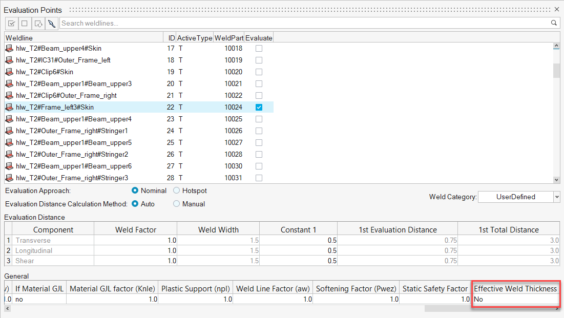
Effective Weld Thickness (Ar)
Ar (resulting weld thickness) is user-defined input. Based on this
parameter, there is a provision to correct the stress values that are
captured from FE in specific sheets of connection according to the formula
specified in General Stress Correction Based on Effective Weld Thickness. This applies only to the stress normal to the weld and
the shear stress. By default the value of Ar is set for the minimum shell
thickness and then you can modify the value accordingly.
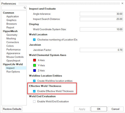
Tip: Turn on the Enable Effective Weld Thickness option in Preferences to
automatically set all weld lines to Yes in the Points Context. The
option is disabled by default.Figure 1.
Direction Details
Longitudinal Direction
Direction parallel to the axis of the weld.
Transverse Direction
Direction perpendicular to the axis of the weld. There are two
directions possible here, one towards the base material and other
towards the web material.
Static Assessment
Use Static assessment to check for yielding/plasticity at weld locations. The Static
evaluation process is carried out for all the evaluation locations based on the weld
type. Von Mises stress component is used for this evaluation process. The maximum
stress value across all the selected loadcases is compared against the material
yield for any particular element.
Static Utilization = Max Von Mises / Material Yield Strength
The above calculation gives the Static utilization factor.
Note: von Mises stress for static assessment is calculated at nominal stress only. If
the hotspot method is applied during fatigue + static assessment, the nominal
method will be applied for static assessment and the hotspot method will be
applied for fatigue assessment.
Restriction: Static assessment
is currently supported for Shell welds only.
General Stress Correction Based on Effective Weld Thickness
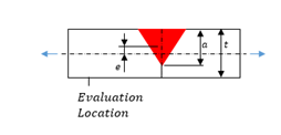
The stress value correction is carried out as shown in the formula
below:
Where:
- Stress value before correction (extraction from element at
evaluation location)
- Thickness of the shell at the evaluation location
- Effective weld thickness
- Intermittent factor, default = 1
- Eccentricity, default = 0
Figure 2.
Influence on Intermittent Factor ()
This factor is used to indicate the partiality of welds. This ratio
describes the length of the weld that has actually been welded. Whenever
the weld connection at any particular location is not
continuous/complete, then you are suggested to modify/reduce this
parameter to take into account the reduced weld material. (1 ≥ ≥ 0)
Influence of Effective Weld Thickness ()
This parameter is used to consider the influence of welds which do not
cover the same cross section area as indicated by the shell element in
the respective evaluation location. It modifies the stress at the
evaluation location based on the ratio to the shell thickness. ( > 0)
- Thickness influence represents the resultant maximum
weld thickness. It varies based on the weld type. this parameter
is location specific.
- Indicates which shell thickness you need for the
calculation of effective weld thickness (). Valid options are and , also location specific. = thickness of welded shell. = min thickness of all connected shells.
Influence of Eccentricity ()
This parameter is used to consider the influence of welds which do not
have the same cross section center as indicated by the shell element in
the respective evaluation location. It modifies the stress at the
evaluation location based on the induced bending stress. If > 0 the stress is increased. If < 0 the stress is reduced. If = 0 there is no influence.
Note: The stress correction does not apply to the longitudinal
stress components from the weld coordinate system.
General Stress Correction is activated when the Effective Weld Thickness option is
set to yes.
This option is activated in the General options section of the Points tool
and is available for all regulations.Figure 3.
The default effective thickness calculated in the weld line browser under location details is based on the
following tables.
Table 1.
Weld
Locations
Effective Thickness
T-Weld
3, 4
0.7
0.7 *
L-Weld
1, 2, 3, 4
0.7
0.7 *
Butt-Weld
1, 2, 3, 4
1.0
1.0 *
Overlap
3, 4
0.7
0.7 *
M-Weld
3, 4, 7, 8
0.7
0.7 *
X-Weld
3, 4, 5, 6, 9, 10
0.7
0.7 *
Table 2.
Weld
Locations
Effective Thickness
T-Weld
1, 2, 5, 6
1.0
1.0 *
Overlap
1, 2, 5, 6
1.0
1.0 *
X-Weld
1, 2, 5, 6
1.0
1.0 *
M-Weld
1, 2, 5, 6
1.0
1.0 *
The default calculated effective thickness can also be manually edited.