
Browsers
Use the browsers in HyperMesh CFD to create, review, and manage the parts,setup parameters, and post-processing entities used in your simulation.
By default, browsers open on the left side of the application. However, you can undock browsers so that they appear as a free-floating dialogs. You can also re-dock browsers on the right-side or the bottom of the application.
Part Browser
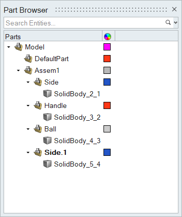
Use the Part Browser to create, organize, and manage the CAE part structure/hierarchy.
To open the Part Browser, click from the menu bar.
The Part Browser displays the relationship between your model's
parts/assemblies (![]() ), solid bodies (
), solid bodies (![]() ), and surface bodies (
), and surface bodies (![]() ).
).
Solid bodies and surface bodies reflect the content within each part. Solid bodies contain a solid and surface bodies contain a group of surfaces. By reviewing the solid and surface bodies, you can get an idea of model.
Bulk Rename
- Adding a prefix or suffix
- Finding and removing a string
- Finding and replacing a string
-
In the Part browser, after selecting multiple parts,
right-click and select Bulk Rename.
A dialog window opens.
-
Select the desired operation from the dropdown menu and then:
- Click the green checkmark
 to commit the change.
 - Click the red x
 to cancel the operation and close the
dialog.
to cancel the operation and close the
dialog. - Press esc to close the dialog without making any changes.
Note: The find and replace operation supports multiple search queries, separated by commas.Figure 2. 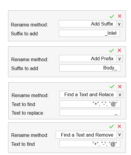
- Click the green checkmark
Setup Browser
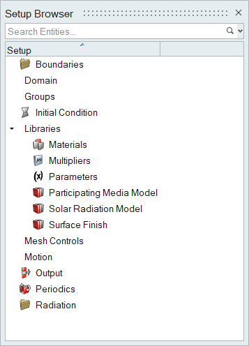
Use the Setup Browser to create, edit, and review setup parameters related to AcuSolve.
To open the Setup Browser, click from the menu bar.
The Setup Browser contains the different categories of parameters that you can use to setup your simulation and any defined instances.
If you right-click on a parameter and select Create/Open, the corresponding ribbon and tool used to create that parameter are activated.
Once a parameter is defined, it is automatically added to the Setup Browser.
Similarly, you can right-click on a defined parameter in the browser and select Edit to quickly jump into the correct tool and change any options.
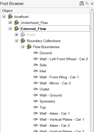
Post Browser
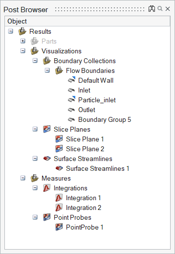
Use the Post Browser to create, edit, export, and review post-processing visualizations and measurements.
The Post Browser contains the model's parts, boundary visualizations, and defined post-processing entities.
You can use the following context menu options, in addition to standard functions like show/hide/isolate/reverse, while in the browser:
- Edit
- Quickly jump into the entity's corresponding tool and change any options.
- Info
- Provides a summary of the number of nodes, elements, and maximum and minimum values of each variable on the surface or dataset.
- Make Current
- Controls which collection new boundary groups are added to.
- Delete Empty Boundary Groups
- Delete empty boundary groups in a collection.
- Duplicate
- Duplicate derived entities with an identical copy of the representation with associated display properties. Useful for creating multiple entities of the same type with minor changes to the entity definition.
- Export
- Provides the capability to export derived entities to a file; .h3d, .vtkhdf, .stl, and .csv are supported. The output files may contain information about the selected geometry and selection of derived representations for a static field or time-dependent field for specific file types.
- Export Database
- Export the entire database including original data and derived representations.
- Create Subcollection
- Available for boundary collections, boundaries, and boundary groups.
- New Collection
- Available on the Boundary Collections heading.
- Remove From Subcollection
- Remove selected from its current subcollection.
- Delete Empty Subcollection
- Delete subcollections that do not contain anything.
Multiple Datasets
Multiple sets of data can be imported into the same session. After opening the first dataset, use to load others.
All datasets are rendered in the browser. The datasets are visible in the modeling window and you can control the visibility of any item of any dataset using the browser.
However, only active dataset entities can be selected in the modeling window and in tools like Slice Planes, Streamlines, and so on. Make a dataset active by right-clicking on in it in the browser and selecting Make Current.
To delete a dataset, right-click on it and select Delete.
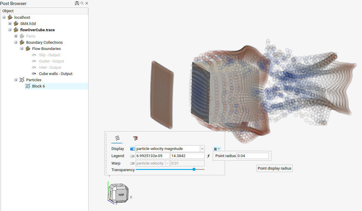
Particle Datasets
HyperMesh CFD Post supports the import of datasets that contain particles. The particles are automatically identified and classified as a separate data type in the Post Browser. Particle datasets have only two different display types available: Points and Vectors
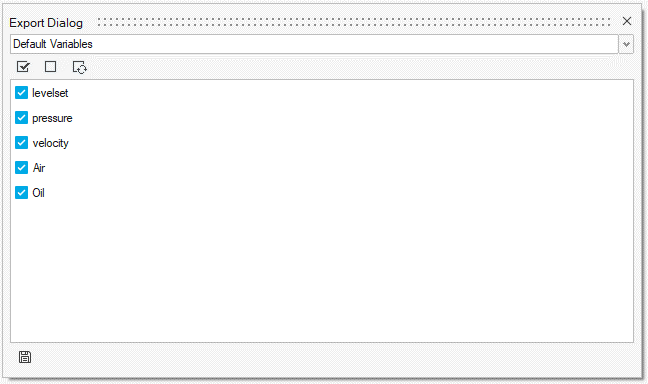
Export Capabilities
HyperMesh CFD Post supports the ability to export derived representations from the Post Browser. Exported representations can be stored for future reference when only a subset of the dataset is needed or if a specific set of quantities are needed to define boundary conditions for subsequent simulations. Multiple file types are supported for export: .h3d, .vtkhdf, .stl and .csv. The Export dialog allows you to select the required variables for storage, and at least one variable must be selected for data-filled files. The selected variables along with the geometric representation of the entity will be stored in the user-defined file. When no variable field is selected during export, .stl is available within the file browser extension list, allowing only the geometry to be written to .stl.
If needed, derived quantities can be selected by using the combo box and selected variables from the Derived Variables section.
| Entities | Time-Dependent | Supported Format |
|---|---|---|
| Boundary Groups | No | .csv, .h3d, .vtkhdf |
| Boundary Groups | Yes | .h3d, .vtkhdf(.series) |
| Derived Representations | No | .csv, .h3d, .vtkhdf |
| Derived Representations | Yes | .vtkhdf(.series) |
| Boundaries + Derived Representations | No | .csv, .h3d, .vtkhdf |
| Boundaries + Derived Representations | Yes | .vtkhdf(.series) |
| Boundaries and | or Derived Representations (No variable selection) |
No | .stl, .csv |
Aerodynamic and Aeroacoustic Model Browser
Similar to the Part Browser, the Model Browser displays and organizes all entities related to aerodynamic/aeroacoustic setup.
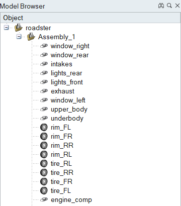
- Find and search for entities in your model.
- Show and hide entities in your model.
- Organize parts into assemblies.
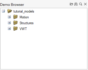
Demo Browser
The Demo Browser (F7) displays a list of demo models packaged with the software.
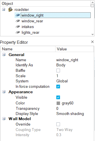
Property Editor
The Property Editor shows all the properties of a selected entity and enables you to edit them.
- Click from the menu bar
- Press F3
- Right-click on selected entities and choosing Properties/Hide Properties from the context menu
Supported Properties
The properties assigned to an object vary based on the type of object.
General
- Name
- Object name. Objects can be renamed in the Model Browser or Property Editor, or by using the right-click context menu.
- Identify As
- Part type in terms of wind tunnel testing: body, heat exchanger in/out/wall, or wheel. This option is also set by means of the Identify Parts tool and the right-click context menu.
- Baffle
- Baffles are two dimensional surfaces that are surrounded by fluid on all sides but do not combine with other surfaces to form a fluid volume. They are used to represent thin regions of solid material that are too costly to explicitly resolve. This option is also set by means of the right-click context menu.
- Scale
- The scale factor of the part with respect to the original geometry that was imported into Virtual Wind Tunnel. This option is also set by means of the Scale tool.
- Group (heat exchanger, wheels)
- Identifies which wheel or heat-exchanger group this part belongs to. You can select different groups from the drop-down list.
Appearance
- Visible
- Indicates whether the selected object is visible (shown or hidden) in the modeling window.
- Color
- Indicates the color assigned to the object when it is displayed in the modeling window.
Click
 to create and assign custom
colors.
to create and assign custom
colors. - Transparency
- Transparency of the selected object, according to a percentage. By default, objects are zero percent transparent.
- Display Style
- Indicates how parts and assemblies are displayed in the modeling window. In addition to the default smooth shading display style, each part can be displayed as mesh lines, or as smooth shading with mesh lines.
Inflow Velocity (Wind Tunnel Only)
- Inflow speed
- The velocity of air at the inlet to the wind tunnel. This velocity is also used as the wall velocity of belts and moving ground if activated.
Boundary Layer Suction (Wind Tunnel Only)
- Active
- Activates the modeling of a boundary layer suction upstream of the point at which the boundary layer begins to grow.
- Location Reference
- The reference location from which boundary layer suction distance is measured. This can be the origin or the wind tunnel's inflow.
- Distance
- The distance from the reference location at which the boundary layer suction is applied.
Tunnel Properties (Wind Tunnel Only)
- Length
- Total length of the wind tunnel, typically designated in meters.
- Width
- Total width of the wind tunnel, typically designated in meters.
- Height
- Total height of the wind tunnel, typically designated in meters.
Tunnel Extents (Wind Tunnel Only)
- X Min, X Max, Y Min, Y Max, Z Min, Z Max
- This value indicates the extension of the wind tunnel with respect to each coordinate axis.
Heat Exchanger Properties (Heat Exchangers Only)
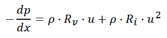
- Inertial Resistance
- The inertial resistance coefficient (
 ) used
to determine the pressure drop across the porous media per the following
equation:
) used
to determine the pressure drop across the porous media per the following
equation: -
-
Where,

- Density

- Velocity

- Pressure

- Location coordinate
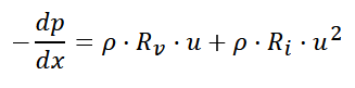
- Viscous Resistance
- The viscous resistance coefficient (
 ) used
to determine the pressure drop across the porous media per the following
equation:
) used
to determine the pressure drop across the porous media per the following
equation: -
-
Where,
- Density
- Velocity
- Pressure
- Location coordinate
Permeability Direction (Heat Exchanger Only)
- Direction X,Y,Z
- Defines the direction in which the permeability is applied.
Wheel RPM (Wheels Only)
- Auto Calculate
- Automatically calculate the angular velocity of the wheel based on the wind speed and location of wind tunnel ground plane.
- Angular Velocity
- Rate of rotation of the wheel.
Wheel Center (Wheels Only)
- Wheel Center X, Wheel Center Y, Wheel Center Z
- Location of the wheel's center in the global coordinate system. The default center is computed based on the oriented bounding box of the part.
Wheel Axis (Wheels Only)
- Wheel Axis X, Wheel Axis Y, Wheel Axis Z
- Wheel's axis of rotation in the global coordinate system. The default axis is computed based on the oriented bounding box of the part.
Fan Rpm (Fans Only)
- RPM
- Rate of rotation of the fan.
Fan Center (Fans Only)
- Fan Center X, Fan Center Y, Fan Center Z
- Location of the fan's center in the global coordinate system. The default center is computed based on the oriented bounding box of the part.
Fan Axis (Fans Only)
- Fan Axis X, Fan Axis Y, Fan Axis Z
- Fan's axis of rotation in the global coordinate system. The default axis is computed based on the oriented bounding box of the part.
Find and Search for Entities
The search bar can be used to find and filter entities in a browser.
-
Enter a string in the browser search bar.
Figure 11. 
Entering this string Returns this result shell All entities/parameters that contain shell in their name. "shell" All entities/parameters with the name shell. -
Press Enter or click
 to execute the search.
- Clear the search string and press Enter or click x to return to the default browser view.
- In the Post Browser/Model Browser,
click
 to find entities without filtering the list.
Click
to find entities without filtering the list.
Click  to search and filter. Navigate to the next and
previous entities that contain the search
string by clicking
to search and filter. Navigate to the next and
previous entities that contain the search
string by clicking  . Find every entity that contains the search string by
clicking
. Find every entity that contains the search string by
clicking  .
. - Click
 on the right side of the search bar to view recent searches.