When possible, HyperMesh CFD checks strive to maintain compatibility with
popular solvers.
2D and 3D Element Checks
The following checks apply to both types of elements, but when applied to 3D elements
they are generally applied to each face of the element. The value of the worst face
is reported as the 3D element’s overall quality value.
Aspect Ratio
Ratio of the longest edge of an element to either its shortest edge or
the shortest distance from a corner node to the opposing edge ("minimal
normalized height"). HyperMesh CFD uses the same method
used for the Length (min) check.
For 3D elements, each face of the element is treated as a 2D element and
its aspect ratio determined. The largest aspect ratio among these faces
is returned as the 3D element’s aspect ratio.
Aspect ratios should rarely exceed 5:1
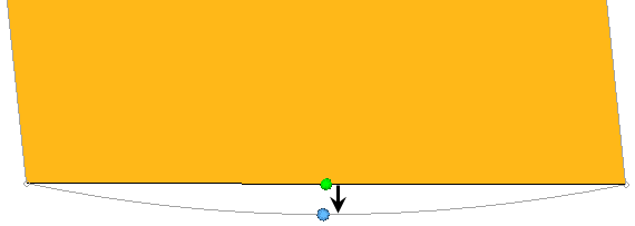
Chordal Deviation
Largest distance between the centers of element edges and the associated
surface.
Second order elements return the same chordal deviation as first order,
when the corner nodes are used due to the expensive nature of the
calculations.Figure 1. Chordal Deviation
Interior Angles
Maximum and minimum interior angles are evaluated independently for
triangles and quadrilaterals.
Jacobian
Deviation of an element from its ideal or "perfect" shape, such as a
triangle’s deviation from equilateral.
The Jacobian value ranges from 0.0 to 1.0, where 1.0 represents a
perfectly shaped element. The determinant of the Jacobian relates the
local stretching of the parametric space which is required to fit it
onto the global coordinate space.
HyperMesh CFD evaluates the determinant of
the Jacobian matrix at each of the element’s integration points (also
called Gauss points) or at the element’s corner nodes, and reports the
ratio between the smallest and the largest. In the case of Jacobian
evaluation at the Gauss points, values of 0.7 and above are generally
acceptable. You can select which method of evaluation to use (Gauss
point or corner node) from the Check Element
settings.
Length (min)
Minimum element lengths are calculated using one of two methods.
The shortest edge of the element. This method is used for
non-tetrahedral 3D elements.
The shortest distance from a corner node to its opposing edge
(or face, in the case of tetra elements); referred to as
"minimal normalized height".
Figure 2. Length Check You can choose which method to use in the Check Element
settings.
Note: This setting affects the calculation
of the Aspect Ratio check.
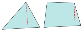
Minimum Length / Size
Minimum element size is calculated using:
Shortest edge
Length of the shortest edge of each element is used.
Minimal normalized height
Is a more accurate, but more complex height.
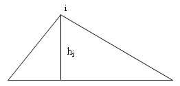
For triangular elements, for each corner node (i), HyperMesh CFD calculates the
closest (perpendicular) distance to the ray including the
opposite leg of the triangle, h(i). MNH = min(hi) *
2/sqrt(3.0). The scaling factor 2/sqrt(3.0) ensures that for
equilateral triangles, the MNH is the length of the minimum
side.Figure 3. Minimal Normalized Height for Triangular
Elements
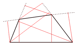
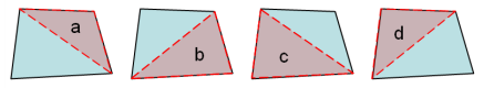
For quadrilateral elements, for each corner node, HyperMesh CFD calculates the
closest (perpendicular) distances to the rays containing the
legs of the quadrilateral that do not include this node. The
figure above depicts these lengths as red lines. Minimal
normalized height is taken to be the minimum of all eight
lines and the four edge lengths, thus, the minimum of 12
possible lengths.Figure 4. Minimal Normalized Height for Quadrilateral
Elements
Minimal height
The same as minimal normalized height, but without a scaling
factor.
Skew
Skew of triangular elements is calculated by finding the minimum angle
between the vector from each node to the opposing mid-side, and the
vector between the two adjacent mid-sides at each node of the
element.Figure 5. Skew of Triangular Elements The minimum angle found is subtracted from ninety degrees and
reported as the element’s skew.
Note: Skew for quads is part of the
HyperMesh-Alt
quality check.
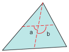
Taper
Taper ratio for the quadrilateral element is defined by first finding
the area of the triangle formed at each corner grid point.Figure 6. Taper for Quadrilateral Element These areas are then compared to one half of the area of the
quadrilateral.
HyperMesh CFD then finds the smallest ratio
of each of these triangular areas to ½ the quad element’s total area (in
the diagram above, "a" is smallest). The resulting value is subtracted
from 1, and the result reported as the element taper. This means that as
the taper approaches 0, the shape approaches a rectangle.
Triangles are assigned a value of 0, in order to prevent HyperMesh CFD from mistaking them for
highly-tapered quadrilaterals and reporting them as "failed".
Warpage
Amount by which an element, or in the case of solid elements, an element
face, deviates from being planar. Since three points define a plane,
this check only applies to quads. The quad is divided into two trias
along its diagonal, and the angle between the trias’ normals is
measured.
Warpage of up to five degrees is generally acceptable.Figure 7. Warpage
3D Element Only Checks
Minimum Length / Size
Two methods are used to calculate the minimum element size.
Shortest edge
Length of the shortest edge of each element is used.
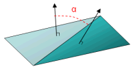
Minimal normalized height
More accurate, but more complex.
HyperMesh CFD calculates the
closest (perpendicular) distances to the planes formed by
the opposite faces for each corner node.Figure 8.
The resulting minimum length/size is the minimum of all such measured
distances.
Tetra Collapse
The height of the tetra element is measured from each of the four nodes
to its opposite face, and then divided by the square root of the face’s
area.Figure 9. The minimum of the four resulting values (one per node) is then
normalized by dividing it by 1.24. As the tetra collapses, the value
approaches 0.0, while a perfect tetra has a value of 1.0.
Non-tetrahedral elements are given values of 1 so that HyperMesh CFD will not mistake them for bad
tetra elements.
Vol. Aspect Ratio
Tetrahedral elements are evaluated by finding the longest edge length
and dividing it by the shortest height (measured from a node to its
opposing face). Other 3D elements, such as hex elements, are evaluated
based on the ratio of their longest edge to their shortest edge.
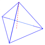
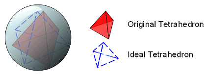
Volume Skew
Only applicable to tetrahedral elements; all others are assigned values
of zero. Volume Skew is defined as 1-shape factor, so a skew of 0 is
perfect and a skew of 1 is the worst possible value.
The shape factor for a tetrahedral element is determined by dividing the
element’s volume by the volume of an ideal (equilateral) tetrahedron of
the same circumradius. In the case of tetrahedral elements, the
circumradius is the radius of a sphere passing through the four vertices
of the tetrahedron.Figure 10.