
ANSYS
ANSYS-specific checks used to calculate element quality for 2D and 3D elements.
2D and 3D Element Checks
These checks apply to both types of elements, but when applied to 3D elements they are generally applied to each face of the element. The value of the worst face is reported as the 3D element’s overall quality value.
Additional element checks not listed here are not part of the solver’s normal set of
checks, and therefore use HyperMesh check methods.
- Aspect Ratio (tria)
- For tria elements, a line is drawn from one node to the midpoint of the
opposite edge. Next, another line is drawn between the midpoints of the
remaining two sides. These lines are typically not perpendicular to each
other or to any of the element edges, but provide four points (three
midpoints plus the vertex).
Figure 1. 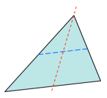
- Then, a rectangle is created for each of these two lines, such that one
line perpendicularly meets the midpoints of two opposing edges of the
rectangle, and the remaining edges of the rectangle pass through the end
points of the remaining line. This results in two rectangles, one
perpendicular to each of the two lines.
Figure 2. 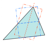
- Aspect Ratio (quad)
- If the element is not flat, it’s projected to a plane which is based on the average of the element’s corner normals. All subsequent calculations are based on this projected element rather than the original (curved) element.
- Next, two lines are created which bisect opposite edges of the element.
These lines are typically not perpendicular to each other or to any of
the element edges, but they provide four midpoints.
Figure 3. 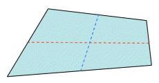
- Third, a rectangle is created for each line, such that the line
perpendicularly bisects two opposing edges of the created rectangle, and
the remaining two edges of the rectangle pass through the remaining
line’s endpoints. This creates two rectangles—one perpendicular to each
line.
Figure 4. 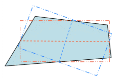
- Interior Angles
- Maximum and minimum values are evaluated independently for triangles and quadrilaterals.
- Jacobian
- Deviation of an element from its ideal or "perfect" shape, such as a triangle’s deviation from equilateral. The Jacobian value ranges from 0.0 to 1.0, where 1.0 represents a perfectly shaped element. The determinant of the Jacobian relates the local stretching of the parametric space which is required to fit it onto the global coordinate space.
- Length (min)
- Minimum element lengths are calculated using one of two methods:
- The shortest edge of the element. This method is used for non-tetrahedral 3D elements.
- The shortest distance from a corner node to its opposing edge (or face, in the case of tetra elements); referred to as "minimal normalized height".
Figure 5. 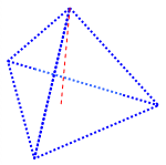
- Angle Deviation (Skew)
- Only applicable to quadrilateral elements, and relies upon the angles between adjacent legs at each corner node (that is, the interior angles at each corner). Each angle is compared to a base of 90 degrees, and the one with the largest deviation from 90 is reported as the angle deviation. Triangular elements are given a value of zero.
- Warping Factor
- Only applicable to quadrilateral elements as well as the quadrilateral faces of 3D bricks, wedges, and pyramids.
- Calculated by creating a normal from the vector product of the element’s
two diagonals. Next, the element’s area is projected to a plane through
the average normal. Finally, the difference in height is measured
between each node of the original element and its corresponding node on
the projection. For flat elements, this is always zero, but for warped
elements one or more nodes will deviate from the plane. The greater the
difference, the more warped the element is.
Figure 6. 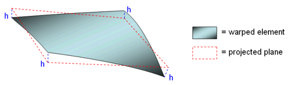
3D Element Only Checks
ANSYS does not use any exclusively 3D checks within HyperMesh CFD, but HyperMesh CFD does use its own when ANSYS is set as the solver. For details on 3D checks, refer to HyperMesh.