
Aerodynamic and Aeroacoustic Measurements
Change the default unit system, create custom units, and measure geometry features.
Unit System of Imported File
It is assumed that the imported surface mesh of the object, for example, vehicle, is in meters (m).
Use the Unit System Selector to change the current unit system.
Recognized Units
Types of units recognized by HyperMesh CFD.
- Unit Type
- Recognized Units
- Length
- mm, cm, m, in, ft, dm
- Mass
- mg, g, kg, ounces, lb, slug, mkg, gkg
- Weight
- N, lbf, kN, MN, GN, kgf, dyn, gf
- Force
- N, lbf, kN, MN, GN, kgf, dyn, gf
- Torque
- N*mm, N*cm, N*m, in*lbf, ft*lbf, kGf*m, dyn*cm
- Pressure
- Pa, kPa, MPa, GPa, N/mm2, N/m2, bar, psi, TPa, kbar, Mbar, lbf/in2, lbf/ft2
- Time
- s, ms, us
- Angle
- deg, rad
Change the Unit System
Use the Unit System Selector to set the current unit system.
Most numbers in a model have units associated with them, such as centimeters or inches for length, and kilograms or slugs for mass. Units are always displayed to the right of numbers wherever they appear.
When you enter a number in a field, the appropriate unit is automatically appended. If you type a unit after a number, the number is converted to the current units. For example, entering 10 in. inside a field where millimeters are the current units results in 254 mm. being displayed.
Units are displayed with mixed capitalization for readability, but you can use any combination of upper and lower case letters when you type them.
- In the lower, right corner of the modeling window, click the Unit System Selector.
-
Select a unit system from the list.
Figure 1. 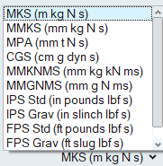
- Optional:
Define a custom unit system by selecting Customize
Units, making your selection in the appearing dialog, then clicking
 .
.
Measure Features
Use the Measure tool to measure geometry features including lengths, angles, and the dimensions of a bounding box.
Click the ![]() satellite icon that appears when you
hover over the Measure tool to view a list of all measures
in your model.
satellite icon that appears when you
hover over the Measure tool to view a list of all measures
in your model.
- Measurements persist after you exit the tool, are listed in the Model Browser, and dynamically update when you make changes to the geometry.
- When you double-click a length measure in the modeling window, it gives you the x, y, z components of the distance vector in the global system.
Measure Bounding Box Dimensions
Use the Measure Box tool to measure the dimensions of the bounding box for a selected part or generated shape.
-
From the Home tools, Measure
tool group, click the Measure Box tool.
Figure 2. 
-
Select the part you want to measure.
Figure 3. 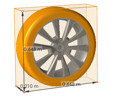
Measure Angles
Use the Measure Angle tool to measure an angle defined by three points.
-
From the Home tools, Measure
tool group, click the Measure Angle tool.
Figure 4. 
-
Click the model to define three sequential points.
Note: Selectable points turn red when you hover over them in the modeling window.A measurement appears and displays the angle between the three points. Point #2 is the vertex of the angle. Dimensions persist after you exit the tool and are dynamically updated as you modify the geometry.
Figure 5. 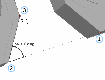
Measure Distance
Use the Measure Length tool to measure the distance between two points.
-
From the Home tools, Measure
tool group, click the Measure Length tool.
Figure 6. 
-
Click the model to define the start point and end point.
A line connecting the two points appears and displays a measurement. Dimensions persist after you exit the tool and are dynamically updated as you modify the geometry.
Figure 7. 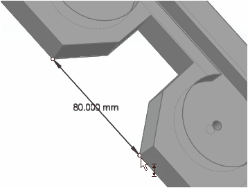
Measure Length
Use the Measure Length tool to measure not only the length of an edge, but also the radius of a circle or an arc, and the diameter or length of a cylinder.
-
From the Home tools, Measure
tool group, click the Measure Length tool.
Figure 8.
-
Hover over a feature to display the corresponding dimension.
- Hover over a straight edge to display the length.
Figure 9. 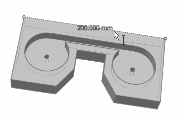
- Hover over a circle or arc to display the radius.
Figure 10. 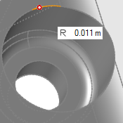
- Hover over a cylinder to display the diameter.
Figure 11. 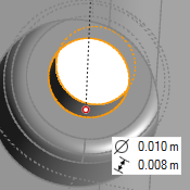
- Hover over a straight edge to display the length.
-
Click the feature to create a measurement.
Dimensions persist after you exit the tool and are dynamically updated as you modify the geometry.