Preferences: Inspire Form
Define preferences for General, Feasibility, Blank Nesting, and, Tryout.
General
Model Setup| Preference | Description |
|---|---|
| FE mesh feature angle | Enter a value for the FE mesh feature angle. The default value set by Inspire Form is 10. |
| FE edge feature angle | Enter a value for the FE edge feature angle. The default value set by Inspire Form is 10. |
| Preference | Description |
|---|---|
| Material library | Enter a default path to the material library .xml file. |
| Preference | Description |
|---|---|
| Run in model directory | Enable this option if you want to store run history in the directory where the model is located rather than the run history path. |
| Run history path | Enter a default path to the directory where the run history is saved. |
| FLD marginal curve offset method | Select Absolute or Relative method to determine offset amount between failure and marginal lines. |
| FLD marginal curve offset value (%) | Specify the amount of offset between failure and marginal lines. |
| FLD loose material bound (%) | Specify the amount of plastic strain to determine possibility of oil canning on part. |
| Preference | Description |
|---|---|
| Mirror results for symmetry | When viewing analysis results, the model is reflected across
existing symmetry planes to allow you to see the full model.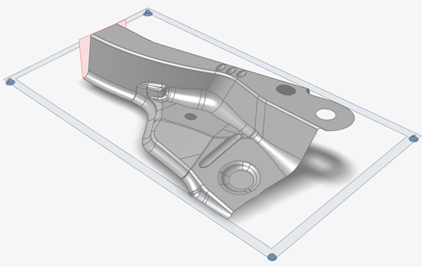 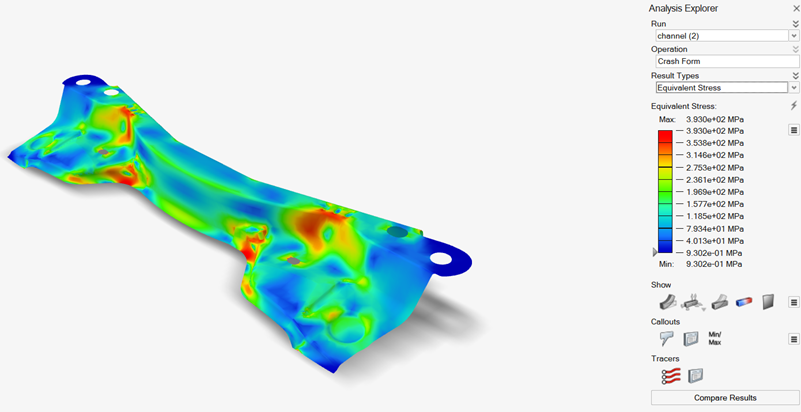 |
| Preference | Description |
|---|---|
| Studio executable | Enter the path to the Studio executable. |
| Preference | Description |
|---|---|
| Report template | The path to the master template for reports. |
Feasibility
Analysis| Preference | Description |
|---|---|
| Friction | Enter a value for the friction coefficient. |
| Shell solution | Select to extrapolate the strain values to the top and bottom surfaces of the blank. |
| Output stamping in CAE solver formats | Enable this option to output results in DYNA, RADIOSS, and
OptiStruct formats in addition to standard formats. Note: These
solver results are used in Springback analysis only by
default. When this option is selected, you can select the
Cutoff plastic strain checkbox and enter
a value in Cutoff value for plastic strain to
limit the strain if it exceeds the specified value.Note: The plastic strain
cutoff is not reflected in results shown in the Analysis
Explorer, but it is included in the results file in other CAE
formats. |
| Default element size | Choose from Coarse,
Medium, Fine,
Custom Uniform Mesh or Custom
Nonuniform Mesh. For the Custom Uniform Mesh option,
you can define a default uniform element size (mm). For the Custom
Nonuniform Mesh option, you can define:
|
| Smooth the flat blank edges | Enable this option to smooth the mesh boundaries when the blank is created. |
| Select all free edges for drawbead by default | Enable this option to automatically highlight all free edges so
that you can easily select them when creating drawbeads. 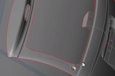 |
| Springback Solver | Use the dropdown menu to select the solver you would like to use
for Springback analysis. Choose from the following options:
|
| Analysis Legend Colors | Description |
| For each result type | Choose the legend colors for plotting results. |
Blank Nesting
| Preference | Description |
|---|---|
|
Enter a value.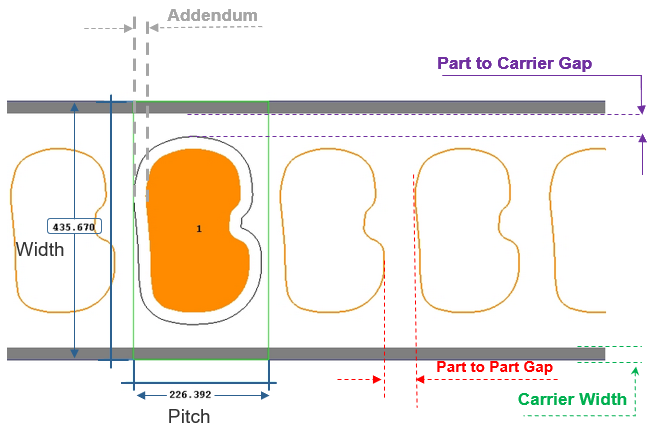 Note: If no value is entered, the coil
width and pitch are optimized for maximum material
utilization. |
|
Enter a value.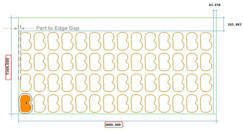 Note: Sheet width and length are
required for nesting on a given sheet stock. |
| Top # of Results | Top number of results to published in the report. |
| Export nested layout in .dxf file format | Set the export format to .dxf. |
| Preference | Description |
| Currency | Choose the monetary currency by country. |
Tryout
| Preference | Description |
|---|---|
| Enable Tryout ribbon on startup if license permits | By default, the Tryout ribbon is enabled. Choose to disable it if you want to reduce the number of units drawn. |
| Preference | Description |
|---|---|
| Automatic tool positioning | Enable this option to automatically position the tools and blank relative to the bottom die during manual or automatic identification. This option is selected by default. |
| Tool offset factor (*thickness) | Default factor for automatic tool creation, spacer, and tool close position. |
| Preference | Description |
|---|---|
| Marginal draft angle | Enter a value for the marginal undercut draft angle. The default value set by Inspire Form is 2. |
| Default element size | Choose from these options:
|
| Gravity mesh coarsen level | Select a custom level to use for Coarse Mesh Gravity to speed up analysis in the Gravity stage. |
| Tool mesh parameter estimation | Select Individual tool to estimate mesh size based on the smallest edge for each individual tool, or All tools to estimate based on the smallest edge across all tools. |
| Tool mesh size | Choose from these options:
|
| Geometry cleanup | Select this option to remove imprints and duplicate surfaces and edges before running a simulation. |
| Solver run mode | Choose:
|
| Default solver precision |
Choose:
|
| Number of local CPU cores | Select Custom to enter a value to specify the number of CPU cores allocated to run an analysis. |
| Output stamping in CAE solver formats | Enable this option to output results in DYNA, RADIOSS, and
OptiStruct formats in addition to standard formats. Note: These
solver results are used in Springback analysis only by
default. |
| Failure strain | Enter a value for failure strain. |
| Preference | Description |
|---|---|
| Number of CPU cores | Enter a value to specify the number of CPU cores the server allocates to run an analysis. Default = 16. |
| Number of CPU cores per node | Enter a value to specify the number of CPU cores per node that exist in the remote server. Default = 16. |
| Memory allocated to the solver (MB) | Memory the server allocates to run an analysis. Default = 8000. |
| Analysis Legend Colors | Description |
| For each result type | Choose the legend colors for plotting results. |